Active program dashboard
![]()
Dashboard
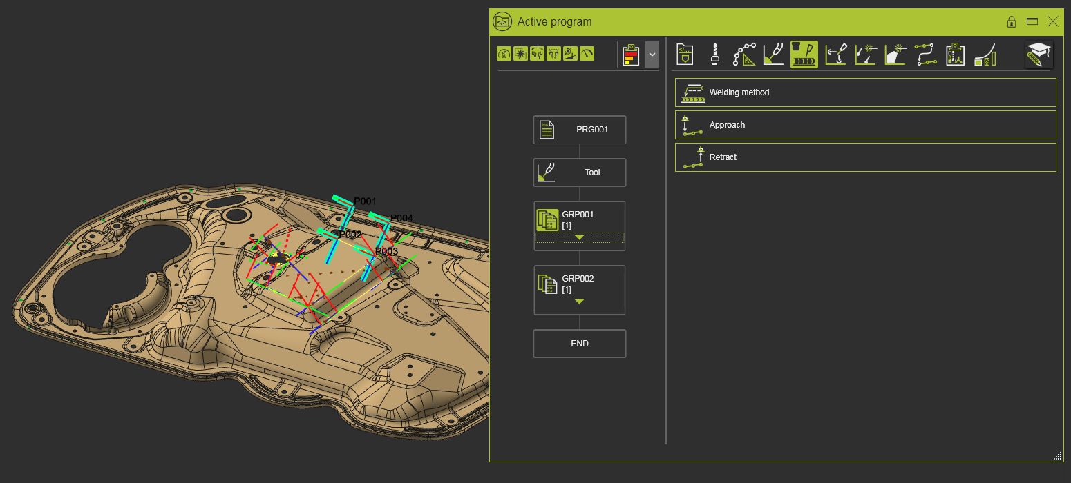
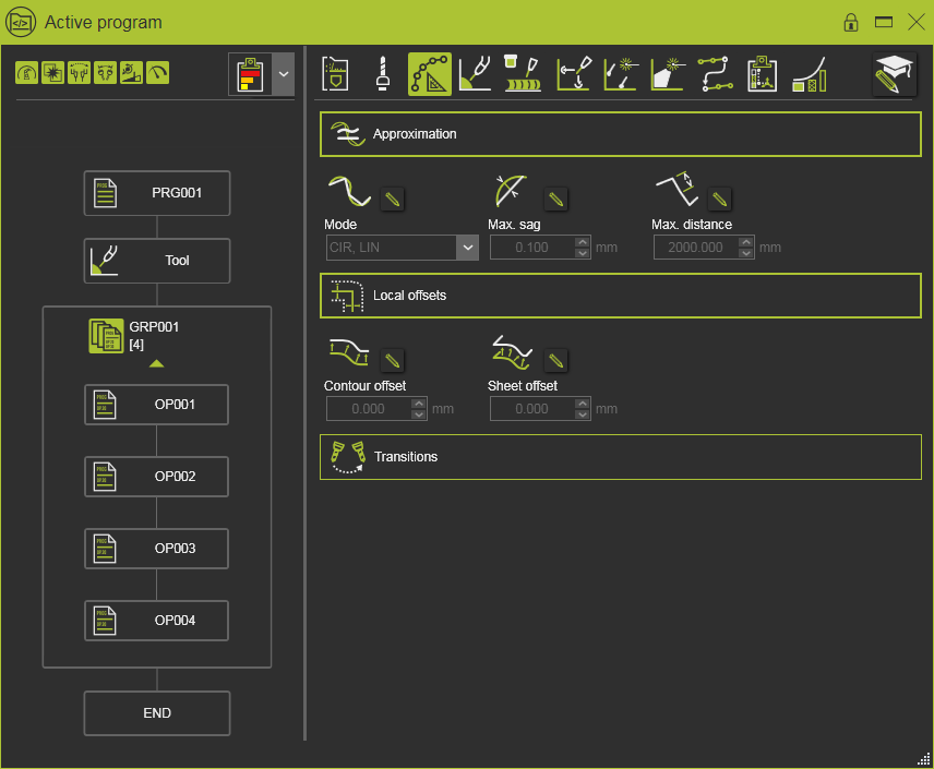
The command opens the Active Program dashboard. In this dashboard the active program and its operations are displayed and can be managed.
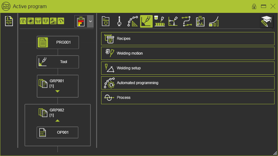
The dashboard has three sections, divided by movable vertical split lines. The most left section is for managing the sub program. The middle section shows the flow chart of the active program. And the right section shows the program attributes.
[link:]
Sub programs
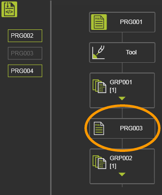
Existing programs can become a sub routine of the active program.
Clicking on the icon will expand the list of available programs, like in the example below. These programs are defined as type Sub in the Program manager dashboard.
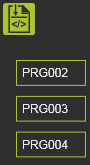
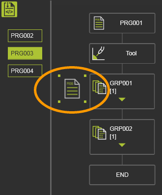
From this list the sub program can be picked and dragged at the desired location in the active program.
 |  |  | ||
| Drag | Drop | Sub program |
A sub program can be inserted multiple times in the active program. Within the program it can be repositioned to another location by picking it up and dragging it to to other location in the program.
When hovering over the sub program after it has been loaded into the active program, a pie menu can be opened.

This section only is displayed when the current active controller in the OLP project does have sub programs.
[link:]
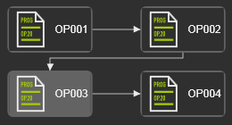
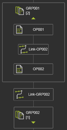
Program flow chart
The program flow chart is a graphical representation visualizing the sequence in which the individual steps of the active program are ordered.
All the graphical objects in the dashboard are mouse sensitive. Hovering the mouse over one of these objects will highlight its content in the 3D View. Selecting a program, operation group or operation opens it to be modified.
Toolpath quality evaluation display
At the top of this section of the dashboard the display settings for the toolpath quality evaluation are placed. With these settings is defined how the result of the quality evaluation is being visualized in the dashboard and in the 3D view.
![]()
The display options are made available also in other dashboards and the use of them is synchronized over these dashboards. They have been described on a separate page, for that the link can be found at the bottom of this page.
Program
The program is the top level of the flow chart
On the flow chart object a pie menu can be opened to execute some support functions for the program.

Here a program can be locked to prevent it against unwanted or unrecognized changes.
In case a program is loaded in a (new) software version that requires a re-computation of the program, for example because of improved geometry approximation algorithms, the system automatically and by default locks the program.
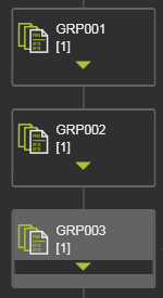
Operation group
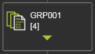
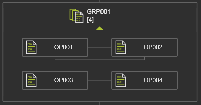
An operation group is a collection of operations
By default the operation group is displayed as a single graphical object. The number in brackets, displayed behind the name, indicates the number of operations within the group. Picking the green triangle will expand the group to show its content of all operations and the order in which they are operated. It goes without saying that picking the triangle again will collapse the group back to its default visualization.
 |  |
On the flow chart object a pie menu can be opened to execute some support functions for the operation group

Within a program, operation groups can be re-ordered to change the sequence in which they are processed. When a group has been selected in the dashboard, the mouse turns into a move sensitive state and moving it now will drag the the group graphics along with it.
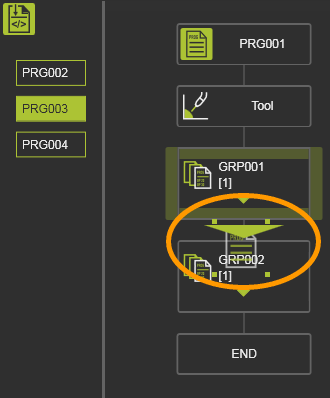
Dragging the group on top of another group will display an arrow marker to show where the dragged group will be positioned relative to the receiving group. Three positions are possible.
 | Dragging the group to the top of another group inserts it in front of this receiving group. | 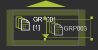 | 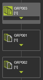 |
| Dragging the group to the bottom of another group inserts it behind this receiving group. | 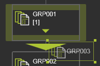 | 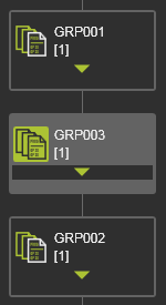 | |
| Dragging the group to one of the sides of another group merges both groups. The added operations are inserted behind the last operation of the receiving group. | 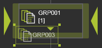 | 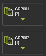 |
With a similar way of handling, operation groups can also be duplicated. When the
![]()
key is pressed before dragging the operation group, the original group remains at its position in the sequence and a copy of that group is placed at the new location to where the group has been dragged and released. The copied group has the same content and properties as the original group, but there is no further relationship between them. After the duplication each group can be modified individually.
| Dragging the group to the top (or bottom) of another group duplicates the group and inserts the duplicate in front of (or after) this receiving group. | | 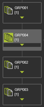 |
Operation
An operation is a single cycle of a certain process step within the program.
On the flow chart object a pie menu can be opened to execute some support functions for the operation.
Operations can be re-ordered to change the sequence in which they are processed. When an operation has been selected in the dashboard, the mouse turns into a move sensitive state and moving it now will drag the the group graphics along with it.

Dragging the operation on top of another one will display an arrow marker to show where the dragged group will be positioned relative to the receiving operation. Within an operation group there are two possibilities to reorder the operation.
 | Dragging the operation to the top of an operation inserts it in front of this receiving operation. | 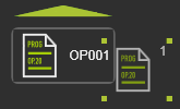 | 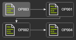 | |
| Dragging the operation to the bottom of an operation inserts it behind this receiving operation. | 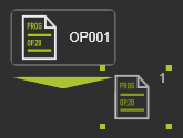 | 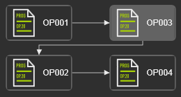 |
In a similar way of handling, operation can also be duplicated. When the
![]()
key is pressed before dragging the operation, the original group remains at its position in the sequence and a copy of that group is placed at the new location to where the group has been dragged and released. The copied group has the same content and properties as the original group, but there is no further relationship between them. After the duplication each group can be modified individually.
Operations can also be reordered to other operation groups or to the program to become a new separate operation group
Operation link
The operation link is the transitional movement between two operation cycles. Moving from the end position of the operation up to the start position of the next operation, without adding any additional position.
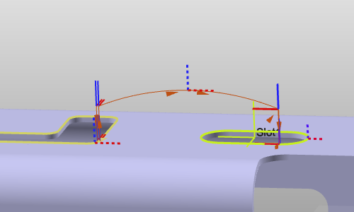
The movement can be defined at program, operation group and at operation level. It is a separate entity in the flow chart.
The operation link is connected to the operation(s). Thus, when an operation, or operation group, is being re-ordered in the flow chart, the operation link moves along with it in such a way that it keeps its transition between the operations in the modified flow chart.
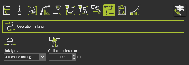
The attributes of the link path can be modified at program level and apply to all present links in the flow chart or can be modified at individual level.
On the flow chart object a pie menu can be opened to execute some support functions for programming the link path.
The operation link may not be applicable in all technologies and therefore not always being visible in the Programming defaults and Active program dashboards.
[link:]
Program attributes
The default values for the different attributes are defined in the Program defaults dashboard. When a program is started, it inherits the applied attributes and their default values. The operation group again inherits the values from the program and the operation inherits the values from the operation group.
When selecting a program step in the flow chart, the corresponding Tech tabs with their attributes are displayed in this section of the dashboard.
At any level in the flow chart the attribute values can be edited and applied to the related downstream steps in the program. Thus; changes made to the program are applied to all downstream operation groups. Changes made to an operation group apply to all its individual operations, not to other groups.
Basically the attribute inherits its value from its parent. But at the same time, at each level of operation group and operation an attribute can be modified. The attribute object shows an additional Edit pencil button. With this button the inherited value can be overwritten and an overwritten value can be reset to inherited.
Keep in mind that moving operations between different operation groups might change an attribute of the moved operation because of this inheritance mechanism. This then happens automatically and without any further notification.
On the attribute itself a Pie menu is present.

Changes made here to many of the attributes here require a recomputation of the toolpath, i.e. program. This can be set to be executed automatically. In this case the program will be recomputed after each modification. To collect changes and then execute the update, the manual recomputation can be set in the Settings. In that case a recomputation command button appears in the top left corner of the 3D space to indicate if a recomputation is required or not.
 |  | |
| No recomputation required | Recomputation required |
![]()
To not overload the user with a huge number of attributes, some of them are hidden by default. With the Expert attributes mode switch, these less used, advanced attributes are being displayed along with the general attributes.
 | 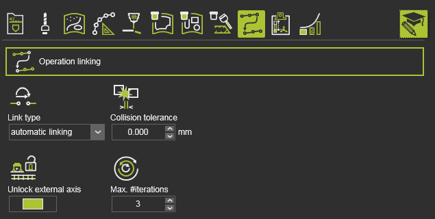 | |
| Normal mode | Expert mode |