Process geometry properties
![]()
Dashboard
The Process geometry dashboards gives a full overview and details of all the process geometry elements of the workpiece. It can be opened from both the Workpiece Preparation and Offline Programming workbench, even although it offers slightly different functionality between them.
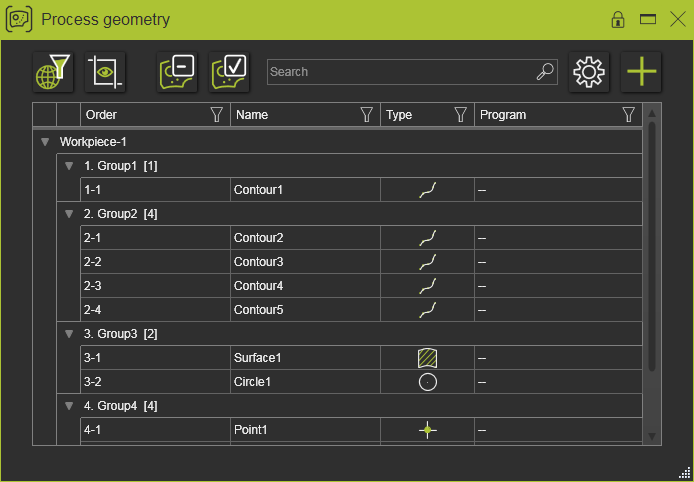
The dashboard is a tabular data set showing all the process geometry elements and their attributes.
The table has four default columns.
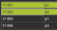
| Order | The sequence of groups and within each group, the sequence of process geometry elements. Group and process geometry identifiers have system default names. The group name, not its number identifier, however can be edited. |
| Name | Names of the process geometry elements. Default names are given initially at creation of the process geometry. The name can be edited by clicking in the name field of the process geometry. Blank names are allowed. |
| Type | The geometrical type of the process geometry indicated by a symbol. The type indicator differentiates between points, contours, surfaces and the regular shape types circle, slot, rectangle, hexagon and keyhole. |
| Program | The program path of a controller when the process geometry has been programmed. Multiple paths can be shown here. |
The table might be extended with additional columns of other known or user defined attributes.
The table rows are to list the present process geometry elements.
The elements are collected in groups. Each group identifier shows its default name and the number of process geometry elements it contains. The group itself can be collapsed or expanded with the triangle symbol in front of the group name.
Display
For comfort or better display, the column width can be modified. Simply grab the right side border of the column and drag it to the left or right to adjust the width.
Each column can be used to sort the table. A simple click in the column will start it. Then a symbol appears to show the sorting sequence.
| First click | Displays an ascending sort of the table. The arrow symbol points up. |
| Second click | Displays a descending sort of the table. The arrow symbol points down. |
| Third click | Displays the default, unsorted table. There is no arrow symbol. |
When sorting the table ascending or descending, the group rows are hidden. Only in the unsorted display the group rows are shown. An exception to this rule is the Order column; sorting in this column always shows the group rows.
The table can also be filtered. Each column has a filter symbol at its right side. Clicking on the symbol opens the filter window.
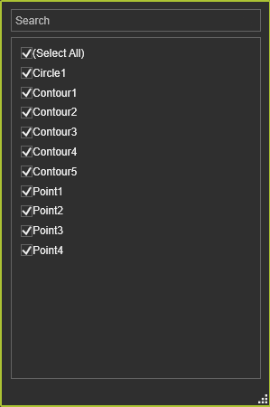
In here the column can be filtered by selecting or deselecting the available items to include or exclude them from the filter. The filter is applied automatically while selecting in this list.
Furthermore, the filter window has the option to reset (Select all) the applied filter or to search for a certain string in the the table and apply that as filter.
As soon as a the table has been filtered, the symbol in the column changes its state to indicate this.
Filters can be applied over multiple columns.
A global (table wide) string based filter can be applied with the Search option.
Typing any string will dynamically search and filter the table for matching result. Deleting the search string will reset the table filter.
At the top left side of the dashboard a few global display switches are present.
| The table filter is also applied to the 3D world. | |
| The camera view re-frames on, i.e. centers the selected process geometry in the 3D world. | |
| Global filter to display only the non-programmed process geometry in both the table and the 3D world. | |
| Global filter to display only the programmed process geometry in both the table and the 3D world. |
Cross selection
Cross highlight when hovering over with the mouse and cross selection between the 3D process geometry and the item in the table is in place. Multiple selection is supported.
When picking a process geometry in the 3D world that is not already visible in the view frame of the dashboard table, its row is brought into view automatically.
Options
![]()
The Options button opens a window.
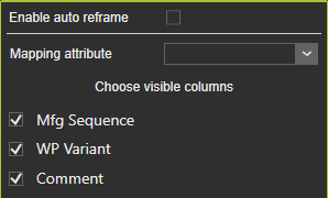
| Mapping attribute | The attribute that will be taken into account when replacing the existing process geometry with a new workpiece or import of PG. The new PG with matching mapping attribute will then replace the existing one. |
| Choose visible columns | Switch to turn on or off the display of the attribute columns in the table. The default columns are always shown. |
In Workpiece Preparation
![]()
The Add new attribute command opens a small window to add a user defined attribute column to the table.
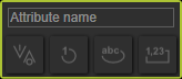
| Attribute name | The name of the new attribute has to be entered here. |
| Attribute type | Selects the type of the attribute: boolean, integer, real or text. |
As soon as the name of the new attribute has been entered, the attribute type selector becomes available. Picking the required type will create the attribute, close the window and adds it to the list.
The attribute name can only be assigned once to a new attribute. Multiple attributes with the same name cannot be created, even not if they are of different type.
Working in this workbench also enables to group and sequence the process geometry elements.
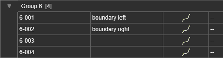
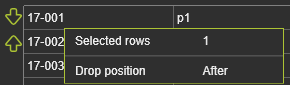
When a process geometry row (or multiple rows) is picked and dragged away just a little, a window appears. It tells how many rows are effected now.
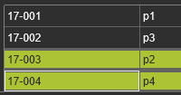
Dragging to another row, in any group, updates the information and shows two smaller arrows in front of that row. The Drop position tells if the dragged row will be placed before or after the row onto which it is going to be dropped.
After the sequencing, the order id of the group is recomputed.
 |  | |
| Before | After |
The drag sequencing can be canceled by dragging away from the Order column. As soon as the sequence window and arrows disappear, the row can be dropped without re-ordering it.
Empty groups cannot exist. Thus, when a group remains empty after moving the process geometry elements, it will be deleted from the table automatically.
When the table is sorted in any attribute column, except in the Order column, the sequencing functionality is de-activated.
Alternatively to the drag functionality, the group and sequencing can also be started in the Pie menu of the selected process geometry.

The Remove command can be executed on group level as well. In that case the group with all its members will be removed. The action can be reversed with the Undo command.
In Offline Programming
Working in the OLP workbench opens the dashboard in read only mode. This means that all attributes, with the exception of the Name attribute, cannot be modified here. Nor can new attributes be added. Also all the sequencing functionality, as available when working in the Workpiece Preparation workbench, is not activated here. The general display features of sorting and filtering can be used.
On the selected process geometry, or on the group row, the Pie menu opens with following content.