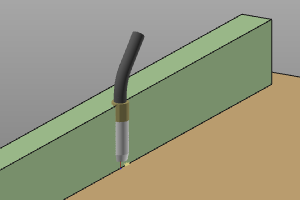
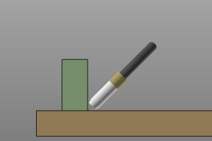
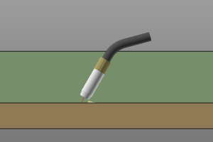
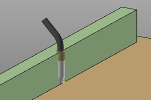
Arc welding
![]()
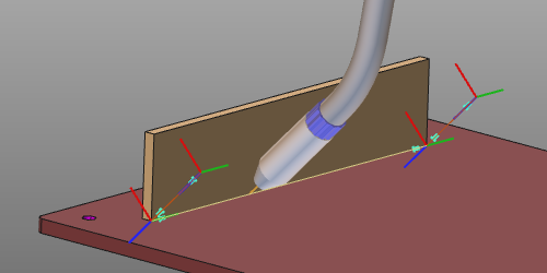
Arc welding operation
Programming a toolpath for arc welding basically generates a (welding) cycle, i.e. an operation, that consists of three sections:
-
approach (off-process)
-
welding process (in-process)
-
retraction (off-process)
The welding cycle is calculated and controlled by the programming attributes and events.
Welding cycles
Arc welding supports different global welding cycles.
| Continuous | Generates a welding seam along the process path from start to end position. |  |
| Stitch | Generates an intermittent welding along the process path, composed of a certain number of smaller welding seams. | 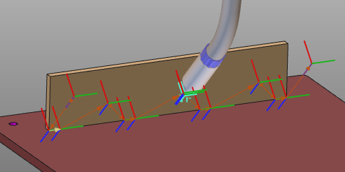 |
| Spot | Generates a welding spot (point) cycle at the defined position(s). | 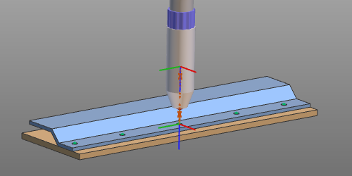 |
On top of these global welding cycles, special features or routines can be applied for maximum optimization, efficiency and performance.
| Box welding | Expands the global welding cycle, where at the start and end position of the path the welding parameters need to be different from the rest of the cycle. For example in corners, to reach the path without collision. |  |
| Process orientation | Works only in situations where an 1- or 2-rotary axis positioner carries the workpiece and the positioner (motion) is connected to the controller. On each toolpath position the positioner axis are manipulated in such a way that the welding tool normal direction (and therefore also the welding seam) is kept in down-hand position. In down-hand position the liquid welding material remains in place. |  |
| Seam calibration | Depending on the method of calibration: Generates a cycle representing the seam calibration operation. For example calibration over touch points. Extends the existing welding cycle with the calibration definition. For example calibration over seam tracking with laser. |  |
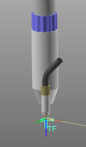
Tool angles
In general there are three tool angles to define the welding torch orientation starting from its nominal position.
 |  |  |
| Work | Travel | Tool |
Tool alignment
Each tool has a tool frame that is used to place it at the toolpath in its correct position and orientation. It is essential that this frame has been aligned with the orientation of the process geometry in order to get a correct result. This alignment is the mapping between the tool frame and the process geometry.
When creating the process geometry, a normal direction and a tangent, i.e. travel direction have been defined.
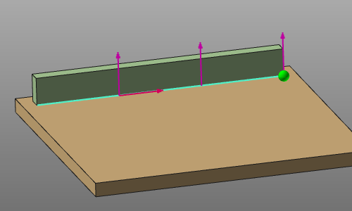
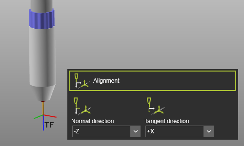
With the Alignment attributes, the tool frame axes have to be mapped with these directions to align the tool correctly.
 |  |
Seam calibration
The welding operation can be extended with a seam calibration operation to determine the welding seam position.
Several calibration methods are implemented:
| Touch sensing with wire Determination of the workpiece by touching (i.e. collision) between the welding gun wire and the workpiece. Calibration of the workpiece position is done before starting the welding process. | 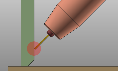 | |
| Touch sensing with nozzle Determination of the workpiece by touching (i.e. collision) between the welding gun nozzle and the workpiece. Calibration of the workpiece position is done before starting the welding process. | 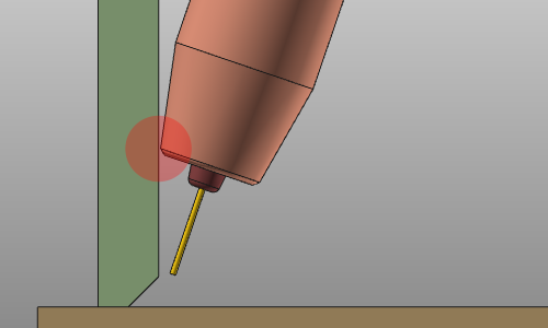 | |
| Seam search with point laser Determination of the workpiece by measuring the workpiece position with a laser. Calibration of the workpiece position is done before starting the welding process. | 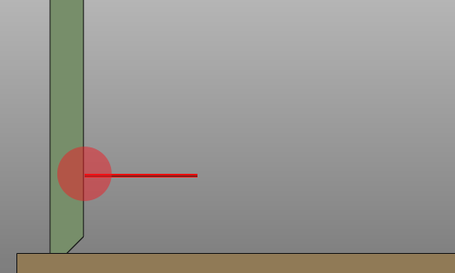 | |
| Seam finding with line laser Determination of the workpiece by measuring, i.e. scanning the start and end position of the welding seam with a 2D/3D line laser. Calibration of the welding seam is done before starting the welding process. | 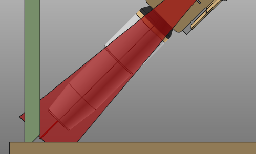 | |
| Seam tracking with line laser Determination of the workpiece by continuous measuring the workpiece position during the welding operation with a line laser. |
Programming attributes
The display of the programming attributes in the Programming defaults and Active program dashboards is defined in a Settings.xml file. With a standard installation, a default file is located at the path <install>\E2Plugin\Technologies\ArcWeldingTechnology\Standard\ControllerSettings.
| Tech tab | Container | Attribute | Description |
|---|---|---|---|
Program base | 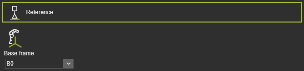 | Base frame | The reference frame of the program. |
Tool data | 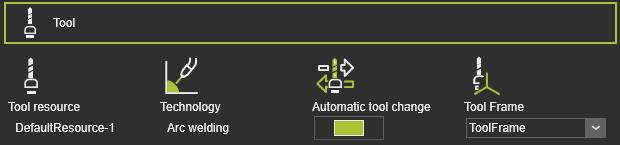 | Tool resource | The name of the tool. |
| Technology | The applied technology. | ||
| Automatic tool change | |||
| Tool frame | The tool frame that runs the toolpath. | ||
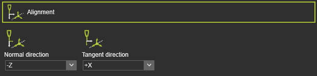 | Normal direction | The alignment of the tool frame Z axis with the normal direction of the process geometry. | |
| Tangent direction | The alignment of the tool frame X axis with the tangent direction of the process geometry. | ||
Manufacturing geometry | Translation in X,Y,Z | The global translation in X,Y or Z direction. | |
| Rotation around X,Y,Z | The global rotation around the X,Y or Z axis. | ||
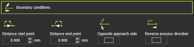 | Distance start point | The distance of the first in-process point from the process geometry start position. | |
| Distance end point | The distance of the last in-process point to the process geometry end position. | ||
| Opposite approach side | Reverse the approach side at the manufacturing start position. | ||
| Reverse process direction | Reverse manufacturing process direction. | ||
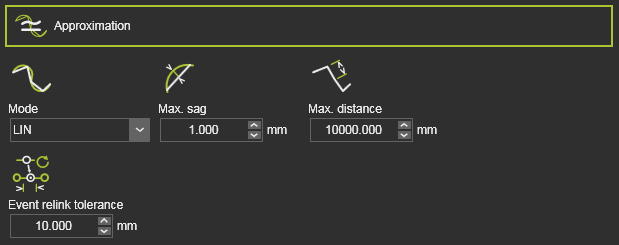 | Mode | Approximation mode. | |
| Max. sag | Maximum allowed deviation between geometry and toolpath. | ||
| Max. distance | Maximum distance between two toolpath elements. | ||
| Event relink tolerance | Tolerance to reconnect existing events after recomputation. | ||
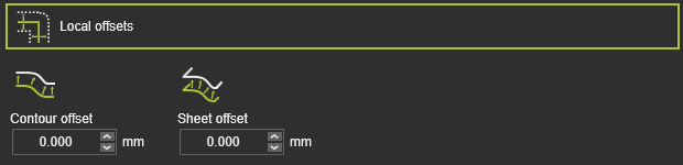 | Contour offset | Offset in bi-tangent direction. | |
| Sheet offset | Offset in surface normal direction. | ||
Technology base | 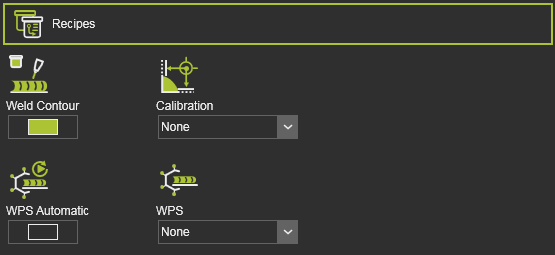 | Weld contour | Defines contour welding operation. |
| Calibration | Selector of weld seam calibration methods. | ||
| (Additional) | Additional calibration attributes. | ||
| WPS Automatic | Automatic assignment of welding procedure specification. | ||
| WPS | Manual assignment of welding procedure specification. | ||
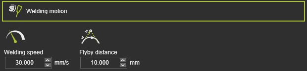 | Welding speed | Welding velocity. | |
| Flyby distance | Motion accuracy on welding path. | ||
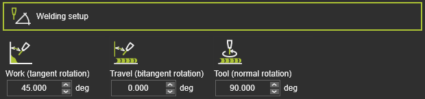 | Work (tangent rotation) | Work angle. | |
| Travel (bitangent rotation) | Travel angle. | ||
| Tool (normal rotation) | Tool angle. | ||
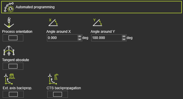 | Process orientation | Maintain tool axes in down-hand direction. | |
| Tangent absolute | Apply tangent absolute direction automatically. | ||
| Ext. axis backprog. | Propagate external axis values backwards. | ||
| CTS backpropagation | Propagate configuration and singularity state backwards. | ||
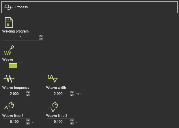 | Welding program | Welding program number. | |
| Weave | Activate weave pattern motion. | ||
| Weave frequency | Frequency of weave pattern. | ||
| Weave width | Amplitude of weave pattern. | ||
| Weave time 1 | Left dwell of weave pattern. | ||
| Weave time 2 | Right dwell of weave pattern. | ||
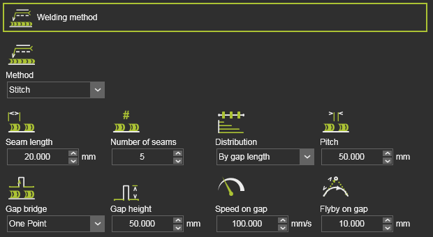 | Method | Continuous or stitch welding. | |
| Seam length | Length of stitch seam. | ||
| Number of seams | Number of stitch seams. | ||
| Distribution | Distribution of stitches along toolpath. | ||
| Pitch | Gap between stitches. | ||
| Gap bridge | Bridge motion between seams. | ||
| Gap height | Height of gap bridge. | ||
| Speed on gap | Velocity on bridge track. | ||
| Flyby on gap | Accuracy to reach bridge height. | ||
| Box welding | Activate box welding process. | ||
| Start / End point offset | Offset start/end position. | ||
| Start / End point tilt angle | Tilt angle at start/end position. | ||
| Start / End length | Transition length at start/end. | ||
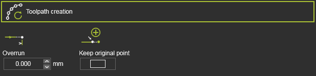 | Overrun | Overrun length value. | |
| Keep original point | Keep or move original point. | ||
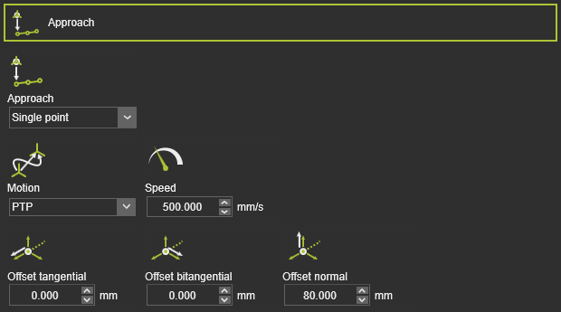 | Approach | Number of approach steps. | |
| Motion | Motion type for approach. | ||
| Speed | Velocity of approach. | ||
| Offset tangential / bitangential / normal | Local offset of approach step. | ||
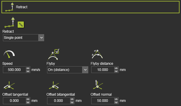 | Retract | Number of retract steps. | |
| Speed | Retract velocity. | ||
| Flyby | Use flyby accuracy or exact retract position. | ||
| Flyby distance | Motion accuracy on retract path. | ||
| Offset tangential / bitangential / normal | Local offset of retract step. |
Program events
The generic arc welding technology has the following programming events:
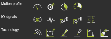
| Motion events | |
|---|---|
| Sets the velocity for the subsequent motions. | |
| Sets the accuracy for the subsequent motions. | |
| Sets a waiting time at the path element for the tool to remain position until moving further. | |
| Sets the acceleration for the subsequent motions. |
| IO signal events | |
|---|---|
| Adds a wait for an input signal event of the active controller. | |
| Adds a set output signal event of the active controller. | |
| Sets an event to synchronize cooperating robots. | |
| Sets a port of a resource. | |
| Waits for a port of a resource. | |
| Sets a signal of a mechanical parent adapter to create or delete a mechanical connection during simulation. |
| Technology event | |
|---|---|
| Inserts a comment. |
| Activates and defines the motions to identify the seam location. | |
| Powers on the welding arc. | |
| Powers off the welding arc. | |
| Assigns the weld seam calibration to the welding operation(s). | |
| Activates the laser seam tracking. |
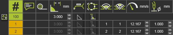
Process model
The operating conditions of the welding process is given a welding ID. In the controller process table these welding IDs can be inserted with their specific process values. When the welding ID is set for the seam (process geometry), the controller will apply the corresponding process values for that welding operation.
In this welding process model also can be specified if a certain welding setup uses multiple layer welding.
Auxiliary commands
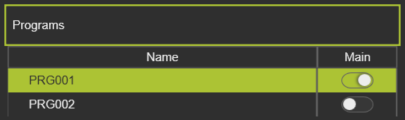
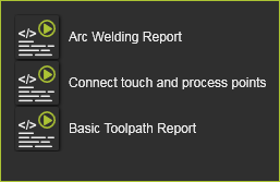
The default arc welding technology delivers a few auxiliary commands that can be executed on the program id, as listed in the Program manager dashboard.