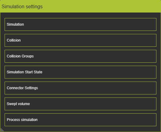
Simulation settings
![]()
Dashboard
With the Settings command several specific simulation options can be defined. The Settings are divided in several levels.
Simulation
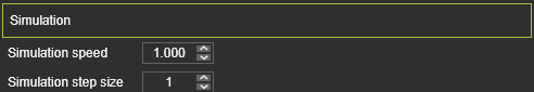
| Simulation speed | The display speed on screen of the simulation. A value between 0,1 and 10 can be set. Under equal circumstances, a simulation speed of 10 roughly runs 10 times faster on screen than with speed = 1. |
| Simulation step size | The step size when manually stepping back or forward through the simulation. |
![]()
It is recommended to keep the simulation speed relatively low when the simulation is run in combination with collision analysis. Some smaller collisions or narrow escapes might not be seen adequately when the simulation runs fast.
Collision
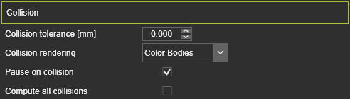
| Collision tolerance (mm) | The tolerance between two groups of when a collision is detected. The value is the distance between the groups. A value = 0 corresponds to a contact. |
| Collision rendering | Option if the colliding geometry has to be colored or not when collision is detected. |
| Pause on collision | Check box to stop a motion picture simulation at the position where a collision has been detected. To continue the Play button has to be pressed again. |
| Compute all collisions | At each step of the simulation the collision checks are executed and multiple possible colliding cases may occur at any position of the simulated bodies (i.e. collision groups). With this option off, the collision analysis at the simulation step stops as soon as a collision situation has been detected, regardless if other collisions may occur at the same time. With the option on, the collision computation continues and displays all colliding situations that occur at that simulation step. See the example below. |
 | 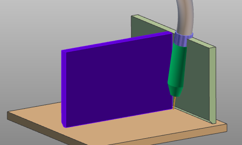 | 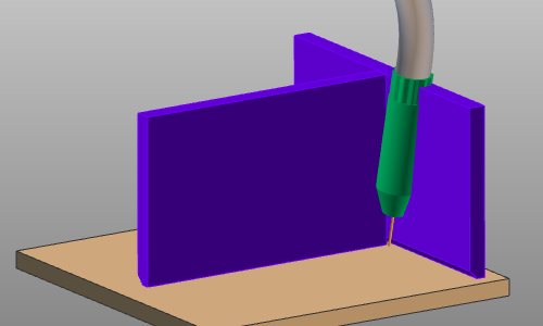 | ||
| Situation | Compute all collisions: Off | Compute all collisions: On |
Collision groups
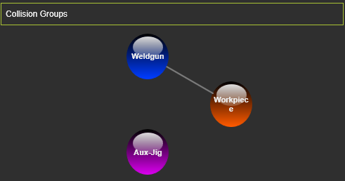
In this container the defined collision groups and checks are displayed.
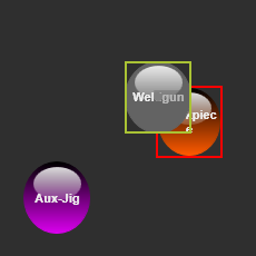
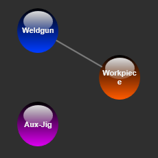
Each group is represented by a bullet graphic that has the same color as the geometry has in the 3D View. A white line connecting two groups displays the check definition.Hoovering over such a bullet highlights the corresponding group in the 3D View.
The check definitions can be managed here. Picking a group bullet displays an activation rectangle around it. Now the bullet can be dragged to another bullet to release it on top. If no check connection was present, it will be created. If a check connecting was present, it will be deleted.
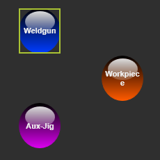 |  |  | ||
| Pick | Drag | Check defined |
![]()
Collision groups themselves are directly managed in the 3D View with the Operation mode Collision set active.
In this container it is also possible to remove a defined collision group. With use of the ![]() key the selected group will be removed from the definitions.
key the selected group will be removed from the definitions.
Simulation start state
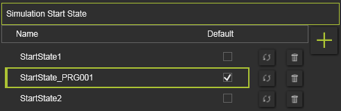
The default start state can be defined here just by setting the Default check box. It is obvious that only one state can be set default.
At creation, the start state is given a standard name. This name can be modified by double clicking on it and altering the text.
Start States can be managed here.
| Add | Add the current position of all components as a new start state. | |
| Remove | Remove the selected start state from the list. | |
| Update | Update incomplete state state information. |
![]()
Although it does not set the start state as default, selecting a start state in the list will change the 3D layout to this state.
Connector settings
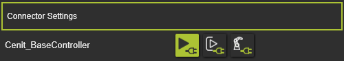
In this container a list of all available connector instances is displayed. For each controller in the project, the active simulation connection can be defined here, in which the simulation will be run.
Swept volume
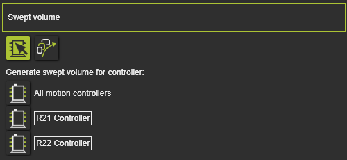
In this container is defined for which controller (programs) the swept volume is going to be created. It enables to create only those swept volumes that are related to the selected controller.
There are two modes to switch in between:
| Controller selection From the list of present controllers, select the controller(s), with its programs, for which the defined swept volumes are being computed. Controllers can be selected or deselected simply by pressing their representation button in front of their name. | |
| All swept volume definitions For all swept volume definitions in the project the computation is being executed. |
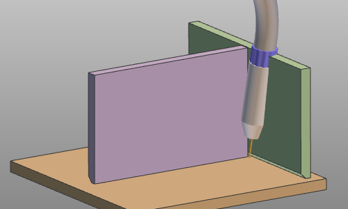
Process simulation
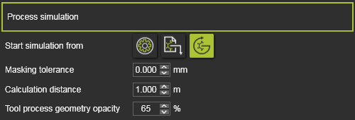
Here the process simulation settings are defined.
| Start simulation from | When the simulation is started, the physical parameter(s) on the process simulation object is calculated. The starting value of that parameter can be: |
| Masking tolerance | When overlapping elements are masking the process simulation object, the simulation will ignore these masking elements that lie within the tolerance field. |
| Calculation distance | The maximum length, as seen from the technology reference frame, to where the tool process model reaches. For example the cone length of a spraying brush. |
| Tool process geometry opacity | The opacity of the 3D geometry that represents the tool process model during the simulation, like for example a spray painting cone. |