Fillet weld contour based process geometry
![]()
Command
With the Create fillet weld process geometry command, this special type of process geometry can be created.
It starts a dedicated search method to find the common, i.e. intersecting contour of two (solid) bodies. A typical situation in arc welding projects.
The functionality only works on workpieces that are built form multiple bodies. Assemblies of different, multiple workpieces cannot be processed with this command.
Create
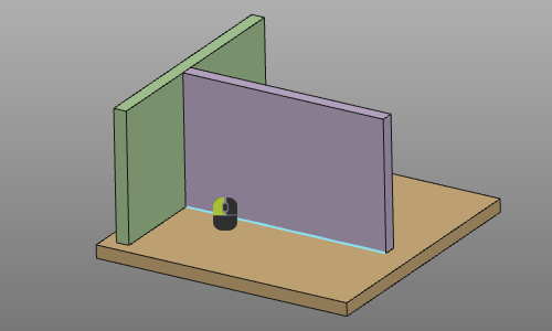
The selection of the contour supports a single element selection or a contour search to find the maximum possible solution. Calling the pie menu in the 3D View enables to switch between these modes.

Picking an element of the contour automatically results in the either that single element or the complete contour, without any further interaction of the user.
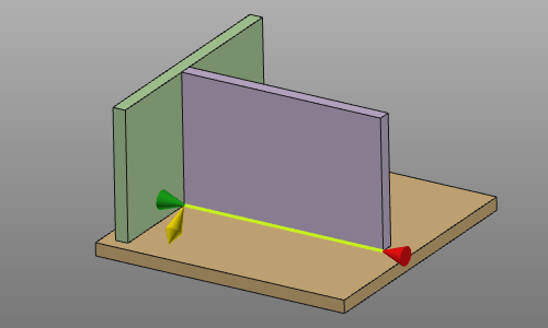
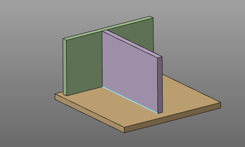 | 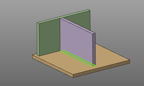 | |
| Start | Result on active search mode |
In the search mode, the contour search has been stopped automatically when other bodies would cause some kind of interference or sort of collision. And furthermore the result process geometry has been given some additional attributes that apply when programming a toolpath on it. These attributes are displayed in the table of the process geometry dashboard.
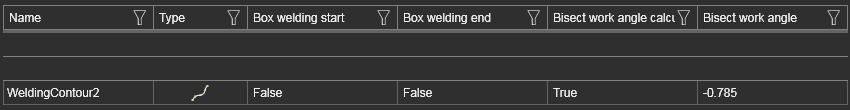
The specific attributes concern:
-
Box welding computation at the start or end position of the toolpath.
-
Work angle of the tool is calculated as 1/2 * angle between the bodies.
If this contour search method does not give the expected result, due to multiple possible solutions, or because the geometrical information (the bodies) cannot return a result, then the process geometry has to be created with the regular contour process geometry functionality.
Edit
For the moment, an existing fillet weld process geometry cannot be modified in context of contour modifications. Of course the process geometry object can be removed.
Its attributes for the offline programming can be modified in the process geometry dashboard.
Automatic generation of toolpath in OLP
The creation of process geometry is also enabled in the OLP workbench. This is for convenience, not having to switch between Workpiece Preparation and OLP workbench constantly.
When creating a fillet weld process geometry while working in the OLP workbench, not only the process geometry is computed. Within the same operation a toolpath will be generated immediately after that, without any further interaction of the user. The toolpath is being computed with the programming defaults as set for the currently applied technology and with taken into account its specific attributes. These attributes overrule the programming defaults.
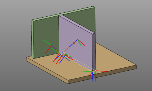
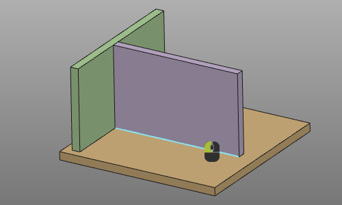
Furthermore; when selecting the contour, the position on that contour when picking it determines the direction of the operation. The direction is set at the nearest end limit of and computed along the selected contour element.
 |  | |
 | 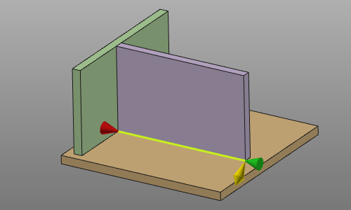 |