Welding contour process geometry
![]()
Command
With the Welding contour process geometry command, a dedicated contour process geometry for arc or laser welding can be created. It is a regular contour, generated over other search methods and including some additional, welding specific features.
The process geometry definition includes two different methods.
| Contour search Searches for a contour when a curve element has been picked. | |
| Contour projection Projects a surface boundary onto another surface. |
Below the search method other available options are displayed.
| Arc weld seam Opens the weld seam cockpit to set the welding seam process information. Specific for the arc and laser welding technologies. |
Contour search method
![]()
This method only works on workpieces that are built form multiple bodies. Assemblies of different, multiple workpieces cannot be processed with this method.
The selection of the contour supports a single element selection or a contour search to find the maximum possible solution, i.e. up to where a box condition occurs. Calling the pie menu in the 3D View enables to switch between these modes.

Picking an element of the contour automatically results in the either that single element or the complete contour, without any further interaction of the user.
 |  | |
| Start | Result on active search mode |
The method knows one option.
| Search all edges | When the search mode is off the process geometry is automatically created on the selected (single) contour element. When the search mode is activated, the contour selection starts the search to find the complete possible fillet weld solution. The contour search stops automatically when other bodies would cause some kind of interference or sort of collision. |
 |  | |
| Off | On |
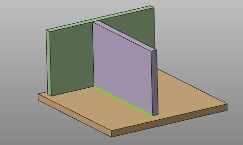
![]()
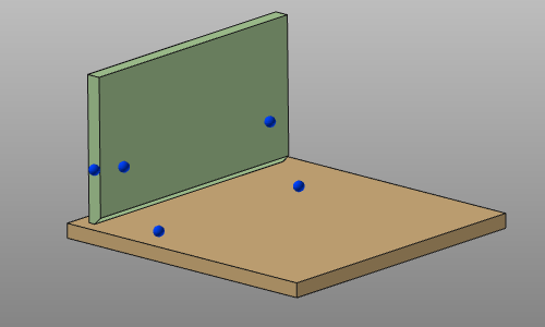
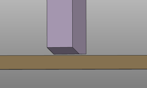
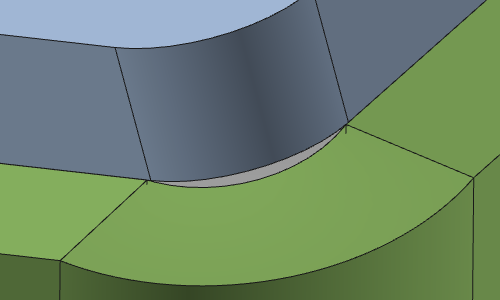
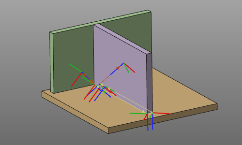
This method is intended for situations where the to be welded parts do not have a common edge to generate the process geometry from. This usually appears in cases where the bodies are not perfectly placed against each other, where the workpiece is built from multiple bodies or assemblies, or where the shape of the welding part does not have an obvious welding contour, like in the example below.
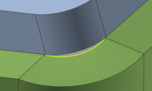
The principle of this method is that the (nearest) surface boundary edge will be projected onto another surface to build the welding contour.
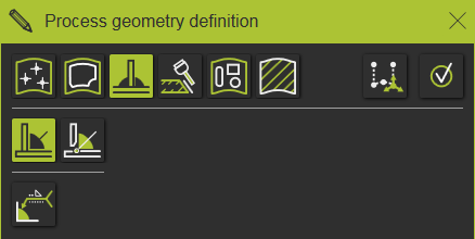
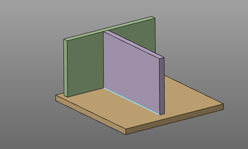
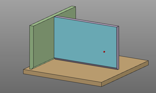
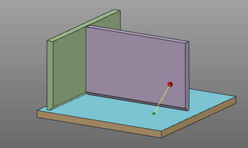
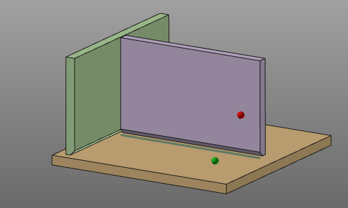
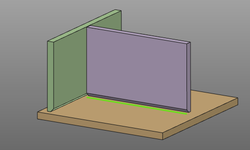
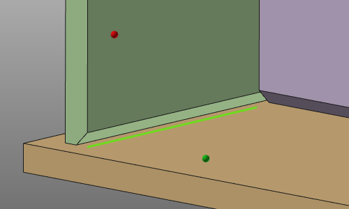
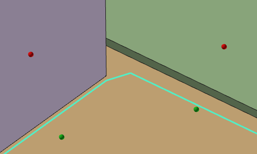
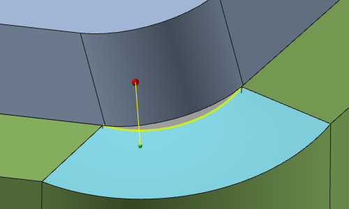
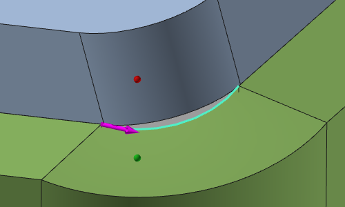
When the command has been started, a small sphere appears at the mouse pointer. Usually, the first the pointer has to be dragged onto the initial surface that has the contour to build the process geometry. Picking, but keeping the mouse button down will select that surface, which is marked with a red sphere. With the mouse button down, the pointer drags onto the surface onto which the contour will be projected. A drag beam appears. Releasing the mouse on that surface leaves a green sphere as indicator; a pair has been built and the resulting projection contour is being displayed. Confirmation in the Process geometry definition panel, with the ![]() key or with the confirm command in the pie menu, will generate the process geometry.
key or with the confirm command in the pie menu, will generate the process geometry.
 |  |  |  | |||
| Pick initial surface | Drag on to receiving surface | Release to build result | Generate process geometry |
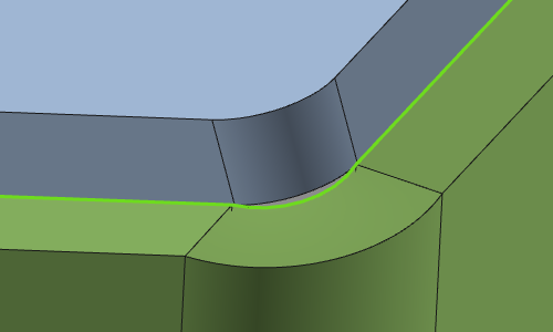
While projecting the contour onto the receiving surface, the method will search for the maximum possible solution. Situations like boxing with other parts of the workpiece determine the final result, as shown in the example below.
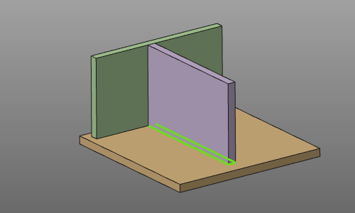
When picking the initial surface, the position on that element determines the direction of the result contour, that later on will be the initial direction while programming an operation on that process geometry. This direction is set at the nearest end position on the contour. The magenta colored arrow indicates the direction.
Clicking the arrow will reverse the direction.
When the picking sequence of the two parts does not result in a projected contour, the system will automatically try to find a solution by projecting in the other direction, i.e. the nearest boundary of the second surface will be projected onto the first surface. Thus; the sequence of picking the two surfaces does not make a difference.
Before confirmation to generate the process geometry, the sequence can be repeated to build a continuous multiple contour solution. With the Undo command the last created projection contour part can be removed again.
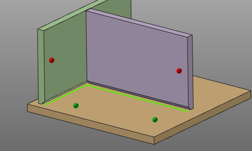
Gaps that appear in a multiple contour solution are automatically closed with a linear segment.
The method knows one option.
| Box welding analysis | When activated, the system analyzes if the process geometry runs into a box situation at the start or the end of the welding contour. In such case the box welding attributes are added to the process geometry. |
The quality of the original CAD data of the workpiece may be the reason why a solution of the projected contour will not be found. In such a case the solution is to first select the contour element and then repeat the pick and drag operation. The contour is used to generate the process geometry and the surfaces are used to calculate the welding angle between the parts.
 |  |  |  | |||
| Case of no solution | Select contour | Pick and drag | Result |
This method can be combined with the standard pick and drag method to build the complete required welding contour.
While working in the OLP workbench and having the tool representation display filter on, the tool rotation definition can be modified on the fly using the arrow keys on the keyboard.
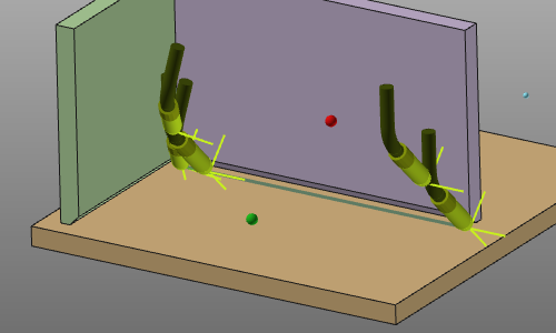
| Left or Right key | Rotates the tool orientation around the normal axis over 90 degrees clockwise or counter clockwise. | 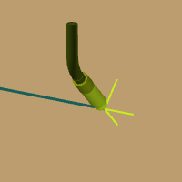 | 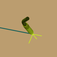 | ||
| Up or Down key | Rotates the tool orientation around the normal axis over 180 degrees clockwise or counter clockwise. | | 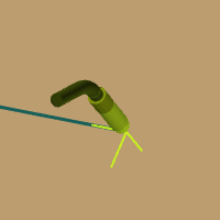 |
The result process geometry has been given some additional attributes that apply when programming a toolpath on it. These attributes are displayed and can be modified in the table of the process geometry dashboard.
The contour search method adds the box welding attributes to the process geometry.
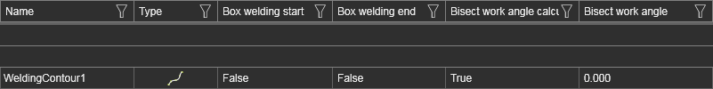
The contour projection method adds the box welding and tool angle attributes to the process geometry.

In combination with the arc weld seam definition, these seam attributes are displayed.

For the moment, an existing fillet weld process geometry cannot be modified in context of contour modifications. Of course the process geometry object can be removed.
Its attributes for the offline programming can be modified in the process geometry dashboard.
The creation of process geometry is also enabled in the OLP workbench. This is for convenience, not having to switch between Workpiece Preparation and OLP workbench constantly.
When creating a fillet weld process geometry while working in the OLP workbench, not only the process geometry is computed. Within the same operation a toolpath will be generated immediately after that, without any further interaction of the user. The toolpath is being computed with the programming defaults as set for the currently applied technology and with taken into account its specific attributes. These attributes overrule the programming defaults.
While defining the welding contour it is possible to include the definition of touch points that are being used for the detection and calibration of the welding seam. These touch points are added by picking them on the surface. The mouse pick position then is measured to become the coordinates of the touch point. With the Undo command the last created touch point(s) can be removed again.