Resource properties
![]()
Dashboard
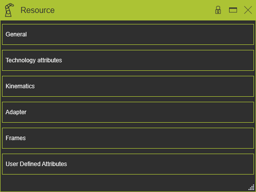
The Resource command opens the dashboard with the complete resource definition, properties and attributes. The information is divided over five containers and can be verified or modified when needed here.
General
This container opens the general information of the resource.
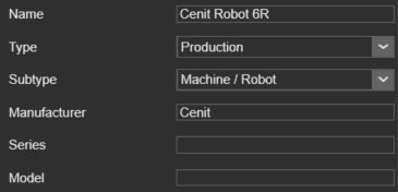
The resource has the following general attributes. At creation of the resource the default values for the attributes are given by the software, depending on the choice of type of resource.The attributes are shown and editable in the dashboard function of the Resource Builder Workbench.
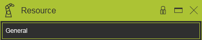
The General container opens with a vertical list with all the defined attributes within the component, shown by their names. Selecting one of them will show its attributes sorted in two groups. A cross highlighting in the 3D View and the dashboard UI appears.
| Attribute | Description | Remark |
|---|---|---|
| Name | The name of the resource | A name for the resource is mandatory. |
| Type | The type of the resource according to the classification. | |
| Sub type | The sub type of the resource according to the classification. | |
| Manufacturer | The manufacturer name of the resource. | Attribute can be left empty. |
| Series | The series name of the resource. | Attribute can be left empty. |
| Model | The model name of the resource. | Attribute can be left empty. |
Depending on the (sub) type of the resource, it has some additional attributes.
| Attribute | Description | Applies to |
|---|---|---|
| Technology | The manufacturing technology for which the resource has been designed or for which it will be set up. 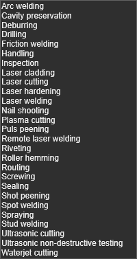 |
Technology attributes
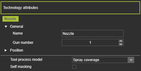
This container opens the technology attributes of the resource. For certain technologies a tool resource is capable to generate a mathematical representation, i.e. model of the manufacturing process. With that model a process simulation can be computed to analyze the effect and impact of that process on a workpiece area, as for example the coating thickness of a painting operation.
The content of this container may be different for each technology. The picture above shows an example.
Because the process model needs a technology reference as origin for calculation, there will be a section with these reference frames. Of each reference frame of the resource the attributes are displayed and can be modified here.
| Attribute | Description | Remark |
|---|---|---|
| Name | The name of the reference. | A blank name is allowed. |
| Gun number | The number of the process outlet. | A tool can have multiple guns, multiple process outlets. |
| X, Y, Z | The X,Y and Z coordinates of the reference. | Coordinates are set to the component’s global coordinate system. |
| Roll(X), Pitch(Y), Yaw(Z) | The roll, pitch and yaw orientation of the reference. | Orientation angles are set to the component’s global coordinate system. |
The second section in the container has the technology specific attributes. This section may not be present.
The container only appears in the dashboard when the assigned technology on the tool resource supports a process simulation model.
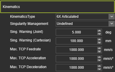
Kinematics
This container opens the kinematic information of the resource. The editor shows the individual joints and their definition. Selecting a joint will cross highlight the joint in the 3D View and its name in the list.
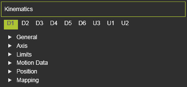
The Kinematics container opens with a list with all the defined attributes within the component, shown by their names. Selecting one of them will show its attributes sorted in six groups. A cross highlighting in the 3D View and the dashboard UI appears.
In case the resource is a production type resource with a kinematic skeleton, the Kinematic container includes some specific behavior attributes.
| Attribute | Description | Applies to |
|---|---|---|
| Kinematics type | The characteristics of the kinematic behavior of the resource. 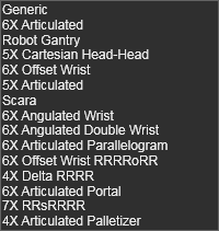 | |
| Singularity Management | The behavior of the resource when it reaches its singularity position. | |
| Sing. Warning Joint | The joint angle to display a warning when the resource almost reaches its singularity position. | |
| Sing. Warning Cartesian | The distance to display a warning when the resource almost reaches its singularity position. | |
| Max. TCP Feedrate | The operation speed of the TCP of the resource; value in mm/s. | |
| Max. TCP Acceleration | The maximum acceleration of the TCP; value in mm/s2. | |
| Max. TCP Deceleration | The maximum deceleration of the TCP, value in mm/s2. |
A kinematic joint has the following base attributes. At creation of the joint the default values for the attributes are given by the software, depending on the choice of type of joint. The attributes are shown and editable in the dashboard functions of the different Workbenches that support the creation of kinematic joints.
| Attribute | Description | Remark |
|---|---|---|
| Name | The name of the joint. | A blank name is allowed. |
| Kinematic type | The type of the joint according to the classification as described above. | |
| Joint type | The class of the joint according to the classification as described above. 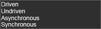 | |
| Current value | The current value of the motion capability, relative to its design position. | Value in mm or degree. |
| Indexed axis | A switch to set if the axis motion, the axis position is indexed, i.e. pre-defined in steps instead of a free motion. When set, the following attributes appear: | Applies only to the asynchronous joint type |
| Step Size | The incremental value in which the axis moves to its next position. | |
| Offset | The starting value as offset from the initial lowest position. The indexed steps are then executed from this offset position. | |
| X, Y, Z | The motion vector of the joint. | Coordinates are set to the component’s global coordinate system. |
| Minimum, Maximum | The minimum and maximum value of the joint motion. | Value in mm or degree. |
| Velocity | The speed with which the joint moves. | Value in mm/s. |
| Acceleration | The acceleration of the joint to reach its velocity. | Value in mm/s2. |
| Deceleration | The deceleration of the joint to stop. | Value in mm/s2. |
| X, Y, Z | The X,Y and Z coordinates of the joint. | Coordinates are set to the component’s global coordinate system. |
| Roll(X), Pitch(Y), Yaw(Z) | The roll, pitch and yaw orientation of the adapter. | Orientation angles are set to the component’s global coordinate system. |
| Define current value | Defines the value that the current position has to represent. This can be different from the value according the design or other source of information. | Value in mm or degree. |
| Offset to math. model | Defines the value that the current position has to be offset from the mathematical model that the software is using to generate the position. | Value in mm or degree. |
Adapter
This container opens the adapter information of the resource. The editor shows the individual adapters and their definition.Selecting an adapter will cross highlight it in the 3D View and its name in the list.
The adapter has the following base attributes. At creation of the adapter the default values for the attributes are given by the software, depending on the choice of type of adapter.The attributes are shown and editable in one of the dashboard functions of the different Workbenches that support the creation of adapters.
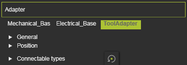
The Adapter container opens with a vertical list with all the defined attributes within the component, shown by their names. Selecting one of them will show its attributes sorted in two groups. A cross highlighting in the 3D View and the dashboard UI appears.
| Attribute | Description | Remark |
|---|---|---|
| Name | The name of the adapter. | A blank name is allowed. |
| Type | The type of the adapter according to the classification. 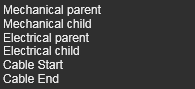 | |
| Capacity | Defines how many adapters can be connected to this one. | Applies only to socket type adapters. |
| X, Y, Z | The X,Y and Z coordinates of the adapter. | Coordinates are set to the component’s global coordinate system. |
| Roll(X), Pitch(Y), Yaw(Z) | The roll, pitch and yaw orientation of the adapter. | Orientation angles are set to the component’s global coordinate system. |
| Defines which classes of components can plug in to this adapter. Selection through the corresponding class icon. | Applies only to mechanical socket adapters. The Reset command switches the definition back to the base setup | |
The resource classes. 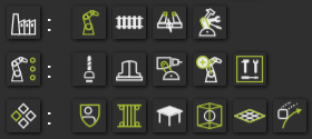 | Picking the category icon sets all components of the category. | |
| The classes humans, controller and workpiece. |
Frames
This container opens the frame information of the resource. The editor shows the individual frames and their definition.Selecting a frame will cross highlight it in the 3D View and its name in the list.
The frame has the following base attributes. At creation of the frame the default values for the attributes are given by the software, depending on the choice of type of frame.The attributes are shown and editable in one of the dashboard functions of the different Workbenches that support the creation of frames.
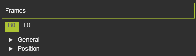
The Frames container opens with a vertical list with all the defined attributes within the component, shown by their names. Selecting one of them will show its attributes sorted in two groups. A cross highlighting in the 3D View and the dashboard UI appears.
| Attribute | Description | Remark |
|---|---|---|
| Name | The name of the frame. | A blank name is allowed. |
| Type | The type of the frame according to the classification as described above. | |
| Vision frame | The frame will be assigned as additional tool reference. | Applies to (resource) tool frames only. Vision frames are used in different applications, technologies or functions for dedicated solutions, like the arc welding seam calibration. |
| X, Y, Z | The X,Y and Z coordinates of the frame. | Coordinates are set to the component’s global coordinate system. |
| Roll(X), Pitch(Y), Yaw(Z) | The roll, pitch and yaw orientation of the frame. | Orientation angles are set to the component’s global coordinate system. |
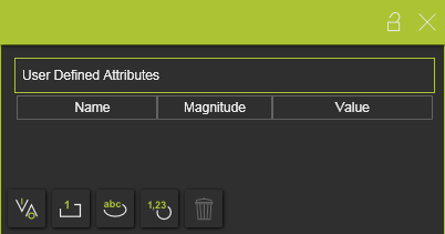
User defined attributes
This container opens the user defined attributes of the resource. The editor shows the attributes and their definition. User defined attributes can be added, modified and deleted here.
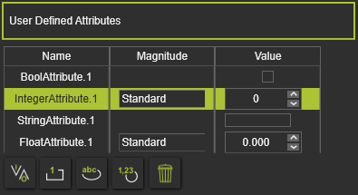
There are four main types of use defined attributes.
| Type | Description | Remark | |
|---|---|---|---|
| Boolean | An attribute that has either the value True or False. | The value is set True by pressing the value button | |
| Integer | An integer number of different magnitudes. For each magnitude the unit is set and displayed automatically. | A drop down list is available to specify the required magnitude 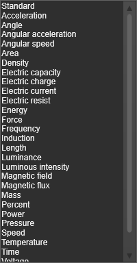 | |
| String | A text based attribute. | ||
| Float | A real number of different magnitudes. For each magnitude the unit is set and displayed automatically. | A drop down list, same as for the integer attribute, is available to specify the specific magnitude. |
The user defined attribute can be added by clicking on the attribute type button. The attribute will be added to the list and is given a default name and value. Selecting the name or value enables to modify it.
The currently active, selected, user defined attribute can be removed by pressing the Delete command button ![]() .
.