Program a contour based toolpath
![]()
Command
The Program toolpath command can be executed on contour based process geometry of the type global contour and welding contour.
When the command has been started, a small window should appear. Here the settings to program the contour are defined.
| Setting | Description | Remark | |
|---|---|---|---|
| Operation connection mode | Program connected operations on the same process contour. | ||
| Autonomous programming | Options if and which autonomous programming methods may be applied while computing an operation. |
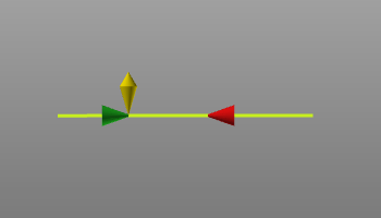
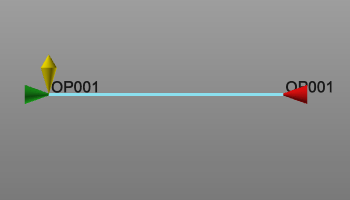
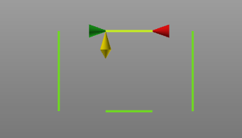
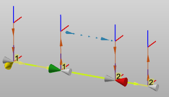
When selecting a contour PG, the so called manufacturing geometry, i.e. the operation, is displayed. It consist of a few symbols located on the PG.
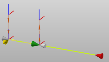
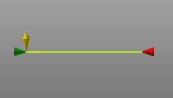 |  | The green cone is placed at the start of the contour, pointing in motion direction. |
 | The red cone is placed at the end of the contour, pointing to the start. | |
 | The yellow double cone, placed at the start, indicates the (normal) side from where the start position will be approached. |
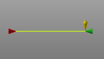
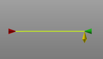
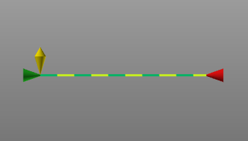
Double click on a marker will switch side. When the start or end position marker is double clicked, the start position becomes end position. When the approach marker is double clicked, the side will swap 180 degrees.
|  |  |
Furthermore the start and end position of the manufacturing geometry along the contour can be modified. By default the whole PG contour will be selected for the to be generated tool path. But with dragging the start or end marker, the manufacturing geometry (and resulting toolpath) can be defined for only a part of the contour.
|  |
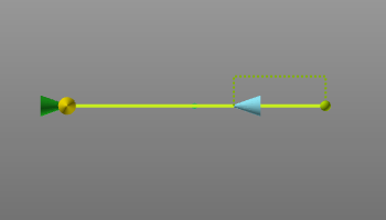
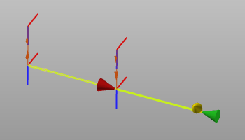
When dragging the start or end marker, a supporting dashed line with attached sphere appears. The sphere indicates the nearest exact limit point on the contour element over which the marker is dragged. Pressing the ![]() key before releasing the left mouse button will place the marker at that exact position.
key before releasing the left mouse button will place the marker at that exact position.
 |  |
Compute the toolpath
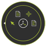
On the selection a Pie menu can be opened:
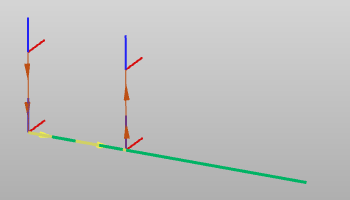
After computation the tool path is displayed. Contour process geometry will be approximated when the tool path is computed. The method and accuracy of the approximation is defined in the program settings. When generating the tool path, a tool path element will be placed at each approximation limit, connected with a path direction line.
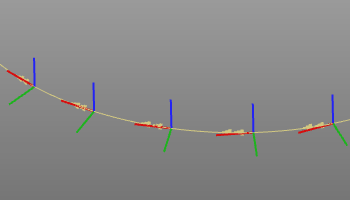
When a circular approximation is applied, an additional tool path element is created in the middle of each approximated arc segment. This tool path element is called a via point and is recognized as dotted axis.
Hovering over the manufacturing geometry, i.e. operation, will show the operation name of the contour.
In case the operation and the process geometry are both displayed (Display filters), the operation contour display turns into a dashed mode to enable that both process contour and operation are selectable for any further action.
Existing contour based toolpaths can be modified. When selecting the toolpath, the manufacturing geometry is displayed and can be adjusted. And also a Pie menu can be opened to start the
command.
Changes made here immediately initiate a re-computation of the toolpath.
Multiple selection and sequencing
This applies to both creating a new toolpath and editing an existing toolpath.
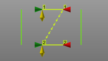
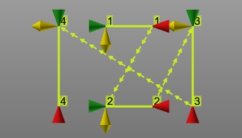
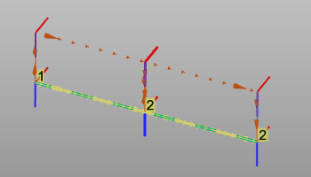
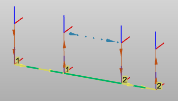
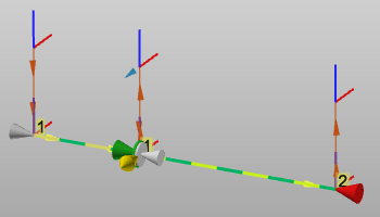
To add a new operation after the last selected contour is simply done by picking another process contour with the ![]() keyboard button pressed. The new selection automatically is added after the last step. The sequence is displayed with a sequence number at each individual contour (operation) and adding an operation connection line from the end of the operation up to the start of the next operation in the sequence.
keyboard button pressed. The new selection automatically is added after the last step. The sequence is displayed with a sequence number at each individual contour (operation) and adding an operation connection line from the end of the operation up to the start of the next operation in the sequence.
 |  |
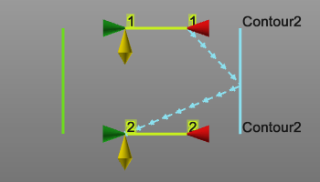
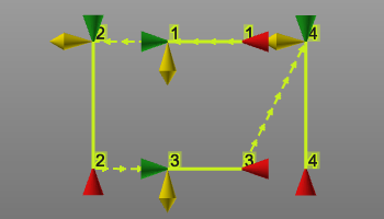
To add a new operation in between two existing ones, the operation connection line is used. This line can be picked with the left mouse button and dragged on top of the new process geometry. Releasing it onto the new contour will add it and updates the sequence.
|  | 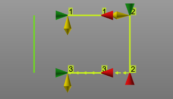 |
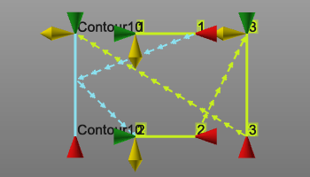
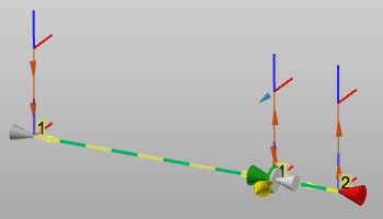
Changing the sequence of the operations works similar to adding an operation in between the existing sequence. Pick the connection line of the sequence step that is going to be modified. Then this line is dragged and released onto the operation to connect to and from where the sequence has to proceed.
 |  |  |
An operation cannot be removed from the toolpath interactive in the 3D View. To do such, the Active program dashboard is to be used.
Connected operations on subareas
As described above, when a process geometry has been selected, the whole contour will be taken by default to program the toolpath. And a part of that contour can be programmed when moving the start or end marker along the contour.
There may be various reasons to want to program the whole contour, but in multiple subareas, i.e. multiple operations. For example when a manufacturing process has to be distributed over multiple machines (controllers), because the processed contour is too long to be reached by one machine.
![]()
With the attribute disabled one can program multiple subareas, multiple parts of the process contour. All these operations are isolated and do not have any relationship with each other, even when the end and start of two operations may lie at the same position. Each operation can be modified independently, by means of its start and end position.
 |  |  |
![]()
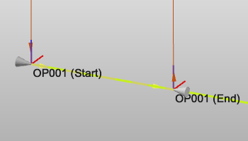
With the attribute enabled one now can program subareas of the process contour that are automatically connected to ensure that no gaps occur. As soon as the process geometry has been selected again to program, the existing operation(s) is being displayed. The start of the new operation continues at the end of the existing one.
 |  |
Or in case the selection is a gap between existing operations, this gap is closed
 |  |
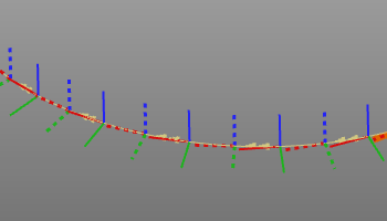
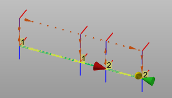
The existing programmed operations on that process geometry are being displayed with grey colored markers. Even if they were programmed in a different program or on another controller.
 |
The new selected part of the contour can be programmed. Without any interaction, the new operation automatically is connected with the existing operation. This is indicated with an additional disc at their common position. It implies that moving the position, from any of both operations, will change both operations..
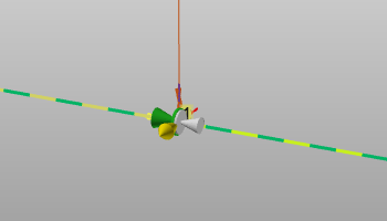 |  |  |
On the operation markers the pie menu can be called:
Arc welding seam detection
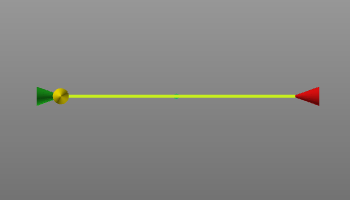
In the arc welding technology there is a possibility to define seam detection touch points while creating the process geometry. When the process geometry includes such touch positions, they will become visible when selecting the process geometry here to generate a toolpath. The yellow spheres represent these touch positions.
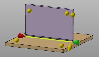
Each position, the yellow spheres, can be repositioned by picking them and dragging to the desired position on the surface. Dropping the sphere, i.e. the mouse location will determine the new coordinates of the touch point.
On existing process geometry it is also possible to define new seam detection touch points. After selection of the process geometry the pie command Program the toolpath has to be started. This will initiate the workflow to define these touch positions on the welding parts. Once finished, a second call of the command will compute the toolpath together with the touch points.
When no touch points are to be defined, the command button simply has to be pressed twice.
Existing touch points simply can be modified by picking and dragging them to their new wanted position. Dropping the sphere, i.e. the mouse location will determine the new coordinates of the touch point. Additional positions can be inserted by picking their location on the workpiece geometry. And removing a position is done by clicking twice on the yellow position sphere.
When done, in the pie the command Program the toolpath has to be started. This will initiate the workflow to compute the toolpath together with the touch calibration points.
Customization script
In general all modifications of the toolpath, the operations (group) or the entire program are done manually. The system does however support the possibility to (partially) automate these modifications.
After the last step in the programming computation a user defined python script can be included to run. With this script not only the last computed toolpath can be modified, but the entire program to which this toolpath belongs. It enables for example to re-organize the different operations, or to include an other naming convention for the operations and toolpath positions.
This dedicated script is named (mandatory) PostProgramProcessGeometries.py and is located in the plugin folder <plugin>\Technologies<technology name>\AuxiliaryCommands\AutoExecute. This can be the default installation plugin or any other configured plugin folder.
The script will only be executed on newly programmed process geometry. Thus, any other change that calls a re-computation of the toolpath or program does not execute the script.