Laser cutting
![]()
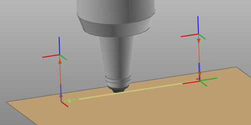
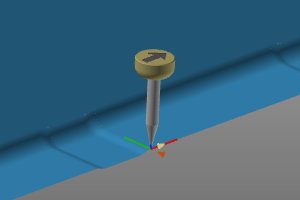
Laser cutting operation
Programming a toolpath for laser cut basically generates a cutting cycle, i.e. an operation, that consists of three sections:
![]()
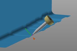
approach (off-process)
![]()
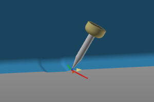
cutting process (in-process)
![]()
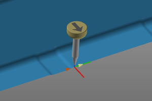
retraction (off-process)
The cutting cycle is calculated and controlled by the programming attributes and events.
Cutting cycles
Besides having the global programming attributes and events determining the calculated toolpath, there are some additional features and routines that can be applied for maximum optimization, efficiency and performance of the laser cut cycle.
| Regular shapes | Geometrical base contours, like circles, rectangles, triangles and such are programmed with predefined cycles for that particular base shape. These cycles may overrule some other attributes. | 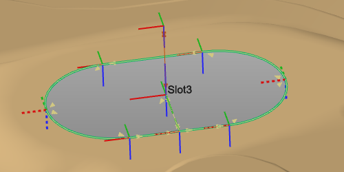 |
| Process orientation | Works only in situations where an 1- or 2-rotary axis positioner carries the workpiece and the positioner (motion) is connected to the controller. On each toolpath position the positioner axis are manipulated in such way that the laser head is kept in a predefined (usually down-) position. As an example this predefined position is for security reasons to have the laser beam always pointing down. |  |
| Side tangent | Contour cutting cycle, where the cutting direction is determined by the tangent surface. | 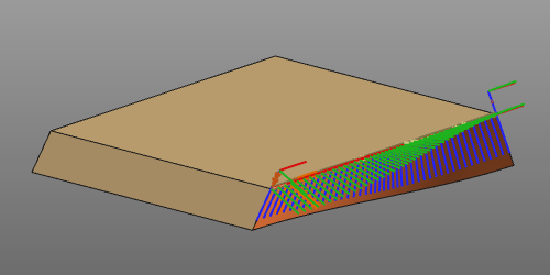 |
Tool angles
In general there are three tool angles to define the laser head orientation starting from its nominal position.
 |  |  |
| Work | Travel | Tool |
Depending on the branding and the configuration of the laser machine, the attributes to define these individual tool angles may not be displayed for manipulation. When not, the tool will be programmed with its nominal position.
Tool alignment
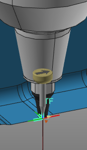
Each tool has a tool frame that is used to place it at the toolpath in its correct position and orientation. It is essential that this frame has been aligned with the orientation of the process geometry in order to get a correct result. This alignment is the mapping between the tool frame and the process geometry.
When creating the process geometry, a normal direction (purple arrows) and tangent or travel direction (red arrow) have been defined.
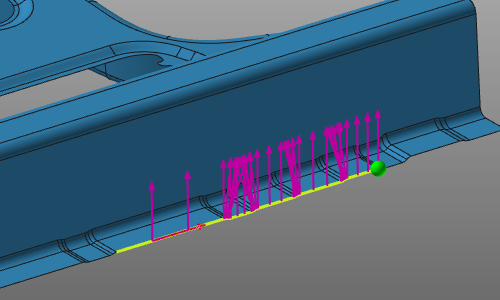
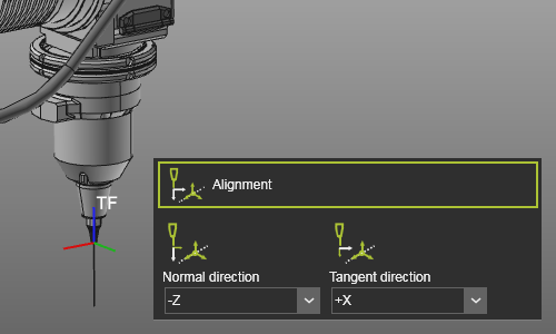
With the Alignment attributes, the tool frame axes have to be mapped with these directions
 |  |
Programming attributes
The display of the programming attributes in the Programming defaults and Active program dashboards is defined in a Settings.xml file. With a standard installation, a default file is located at the path <install>\E2Plugin\Technologies\LaserCuttingTechnology\Standard\ControllerSettings.
For the standard controller the following attributes are defined.
| Tech tab | Container | Attribute | Description |
|---|---|---|---|
| For automatic link path generation | |||
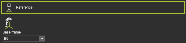 | The program reference information. |
| Base frame | The reference frame of the program. |
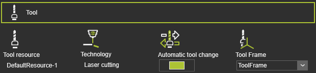 | Tool information. |
| Tool resource | The name of the tool. |
| Technology | The applied technology. |
| Automatic tool change | |
| Tool frame | The tool frame that runs the toolpath. |
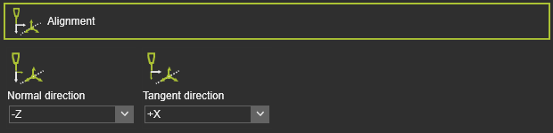 | The mapping of the tool frame axes with the corresponding vectors on the process geometry. |
| Normal direction | The alignment of the tool frame Z axis with the normal direction of the process geometry. |
| Tangent direction | The alignment of the tool frame X axis with the tangent direction of the process geometry. |
| The global transformation of the manufacturing geometry. | |
| Translation in X,Y,Z | The global translation in X,Y or Z direction. |
| Rotation around X,Y,Z | The global rotation around the X,Y or Z axis. |
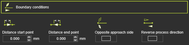 | The boundary conditions on the manufacturing geometry to calculate the toolpath. |
| Distance start point | The distance of the first in-process point from the process geometry start position. |
| Distance end point | The distance of the last in-process point to the process geometry end position. |
| Opposite approach side | To reverse the approach side at the manufacturing start position. |
| Reverse process direction | To reverse the manufacturing process direction, i.e. changes start to end position and vice verse. |
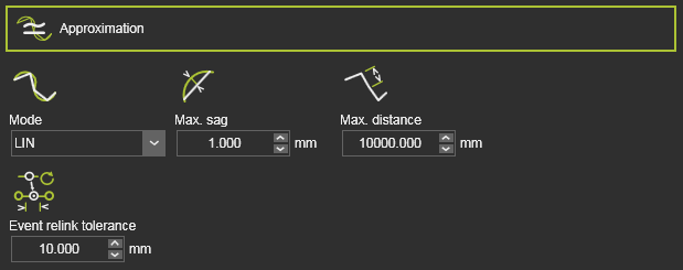 | The approximation of the manufacturing contour to calculate the toolpath. |
| Mode | The mode to approximate the contour. |
| Max. sag | The maximum allowed deviation between the geometry and calculated toolpath. |
| Max. distance | The maximum distance between two in-process toolpath elements along the contour. |
| Event relink tolerance | The tolerance to find the nearest TPE after a toolpath re-computation, to assign the existing event to. This attribute is hidden by default. |
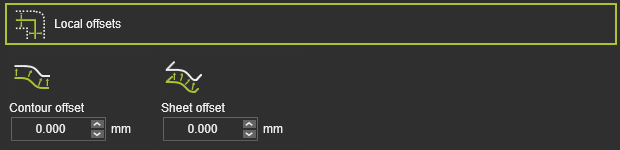 | The offset of the toolpath element from its original location on the manufacturing geometry. |
| Contour offset | The offset in bi-tangent direction. |
| Sheet offset | The offset in (surface) normal direction. |
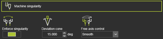 | Machine singularity attributes that are applied when calculating the toolpath, i.e. the algorithms are applied before any further manual enhancement, like teach. |
| Enforce singularity | Enforced singularity optimization of the A and B axis (also named C and A axis) of an NC machine. |
| Deviation cone | Axis with values within the specified cone angle are being optimized. |
| Fixed axis control | Method how both axis are being optimized. |
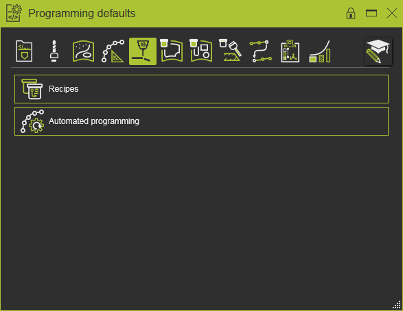
 | Laser cutting recipes. |
| Use regshape | Switch to convert (closed) contours in predefined regular shapes, like circles, rectangles, hexagons, etc. |
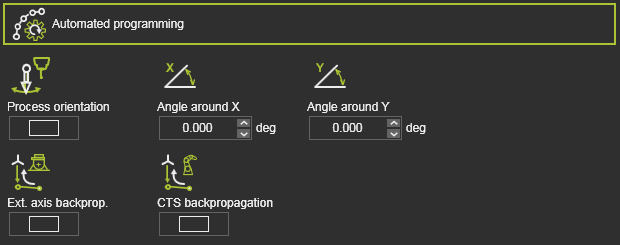 | Additional (optimization) conditions to calculate the toolpath. |
| Process orientation | A switch to optimize each toolpath element with use of the positioner axis to maintain the tool axes in down-hand direction. The condition is only available when a 1-2 axis positioner, carrying the workpiece, is connected to the controller. |
| Ext. axis backprop. (External axis values in approach) | The axis values of an external resource, like a positioner, as been set at the first position of the in-process path, will be propagated backwards up to the approach of that in-process path. |
| CTS backpropagation | The configuration, turn and singularity state of the manufacturing resource, like a laser machine, as been set at the first position of the in-process path, will be propagated backwards up to the approach of that in-process path. |
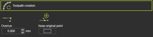 | The overrun (extrapolation) at the contour end when programming an operation. |
| Overrun | The value of the overrun length. A negative value is possible. |
| Keep original point | Switch to define if the original path element (position) is being moved to the overrun position or remains at its original position. In the last case a new path element is created at the overrun position. |
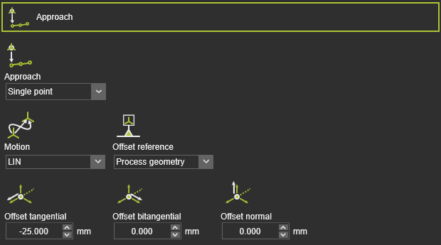 | To define an approach motion towards the in-process toolpath. |
| Approach | The number of approach steps. |
| Motion | The motion type for the approach. |
| Offset reference | The reference to determine the offset directions. |
| Offset tangential / bitangential / normal | The local offset of the approach step from the in-process toolpath start element. |
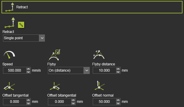 | To define a retraction motion away from the in-process toolpath. |
| Retract | The number of retraction steps. |
| Speed | The velocity of the retract. |
| Flyby | Allow the motion to make use of the flyby accuracy (On distance) or force the motion to the retract position (Off). |
| Flyby distance | The motion accuracy on the retract path. |
| Offset tangential / bitangential / normal | To local offset of the retract step from the in-process toolpath end element. |
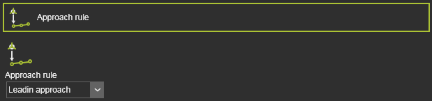 | To define an approach motion towards the in-process toolpath. |
| Approach rule | The predefined approach. |
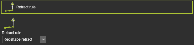 | To define a retraction motion away from the in-process toolpath. |
| Retract rule | The predefined retraction motion. |
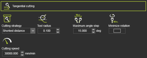 | The definition of the tangential cutting. |
| Cutting strategy | The strategy to compute the side tangent toolpath. |
| Tool radius | The number of stitch seams.. |
| Maximum angle step | The maximum allowed change of the tool angles along the computed toolpath. |
| Minimize rotation | Switch to activate the computation with minimum tool angle rotation. |
| Cutting speed | The velocity along the toolpath.. |
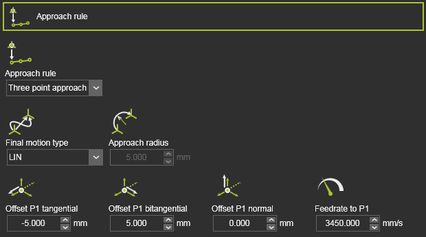 | To define an approach motion towards the in-process toolpath. |
| Approach | The number of steps or method of approach. |
| Final motion type | The motion type for the approach step to the in-process start position. |
| Approach radius | The radius of the above approach step. Applies when the Final motion type is circular. |
| Offset tangential / bitangential / normal | To local offset of the approach step(s) from the in-process toolpath start element. |
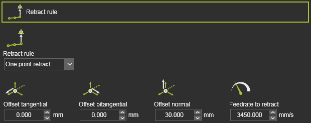 | To define a retraction motion away from the in-process toolpath. |
| Retract rule | The number of steps or method of retraction. |
| Offset tangential / bitangential / normal | To local offset of the retract step from the in-process toolpath end element. |
| Feedrate to retract | The velocity of the retraction step. |
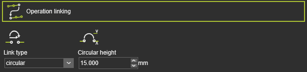 | The way how to move to the next operation. |
| Link type | The motion type to link the operations. 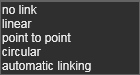 |
| Circular height | The height of the via point to calculate a circular link. |
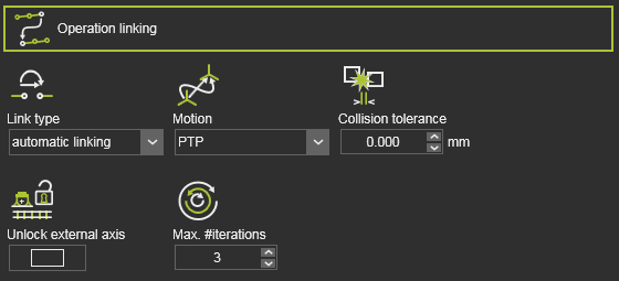 | The way how to move to the next operation for automatic link path generation. |
| Link type | The motion type has been set to Automatic linking. |
| Motion | The motion type along the path. |
| Collision tolerance | Defines the safety distance when generating the link path. |
| Unlock external axis | Use of the entire range of the external axis values for the link path generation. Off: The external axis value can only be changed within the interval given by start and end point of the link path. On: The external axis values are to be considered within the full range of each axis (i.e. are unlocked). |
| Max. #iterations | Defines the maximum number of iterations that the path finding algorithm will run. |
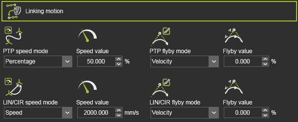 | The way how to move to the next operation. Only valid for automatic link path generation. |
| Speed mode | The motion speed. |
| Speed value | The speed value of the motion. |
| Flyby mode | The flyby motion, i.e. the accuracy to move along the link path positions. 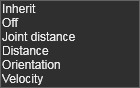 |
| Flyby value | The value of the flyby accuracy (when applicable). |
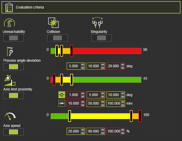 | The toolpath quality evaluation criteria. The exact content may vary per technology. |
| Unreachability | Evaluates unreachable situations of the robot or machine. |
| Collision | Evaluates collision situations. |
| Singularity | Evaluates singularity situations of the robot or machine. |
| Process angle deviation | Evaluates the process angle deviation from its reference value. |
| Axis limit proximity | Evaluates the proximity to the limits of the driven axis. Separated evaluation value range for linear and circular joint axis. |
| Axis speed | Evaluates the axis speed of all driven axis as a (absolute) difference between the start and the end motion between positions. |
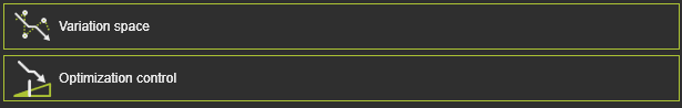 | The automatic path optimization parameters. |
| Variation space | Defines what modifications can be made to the toolpath elements to search for the optimal solution, i.e. minimal costs. |
| Optimization control | Attributes to manage the optimization process. |
Program events
The generic arc welding technology has the following programming events:
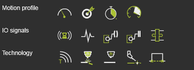
| Motion events | |
|---|---|
| Sets the velocity for the subsequent motions. | |
| Sets the accuracy for the subsequent motions. | |
| Sets a waiting time at the path element for the tool to remain position until moving further. | |
| Sets the acceleration for the subsequent motions. |
| IO signal events | |
|---|---|
| Adds a wait for an input signal event of the active controller. | |
| Adds a set output signal event of the active controller. | |
| Sets an event to synchronize cooperating robots. | |
| Sets a port of a resource. | |
| Waits for a port of a resource. | |
| Sets a signal of a mechanical parent adapter to create or delete a mechanical connection during simulation. |
| Technology event | |
|---|---|
| Inserts a comment. |
| Powers on the laser beam. | |
| Powers off the laser beam. | |
| Sets an inspection position. | |
| Builds a micro tab at the position. |
Auxiliary commands
The default arc welding technology delivers a few auxiliary commands that can be executed on the program id, as listed in the Program manager dashboard.