Contour based process geometry
![]()
Command
With the Contour process geometry command, global contour type of process geometry can be created and edited.
The second row of the definition panel has three contour search modes available to pick from, each with their own specific search parameters.
| Search until Searches and selects the contour between two picked curve elements. | 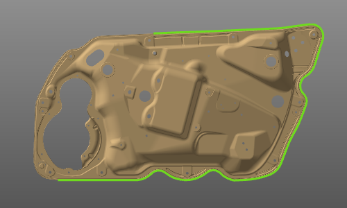 | |
| Closed contour Searches for and selects a closed contour when a curve element has been picked. |  | |
| Surface boundary Searches for all closed inner and outer boundary contours on the selected surface(s). | 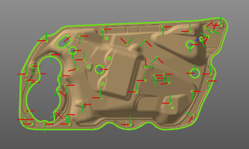 |
Below the search mode several criteria for the search and other options are displayed.
| Arc weld seam Opens the weld seam cockpit to set the welding seam process information. Specific for the arc and laser welding technologies. | ||
| Contour search options Options to define the conditions for the contour search. |
Search along edges
Picking an edge on the workpiece automatically starts the
functionality. In principle there is now difference between the modes
Search until
and
Closed contour
. In the first mode the searched and built contour will be based upon manually picked edges and in the second mode the system automatically will search for a closed contour solution after picking the initial edge on the workpiece. Both solutions can be modified until the wanted contour has been built.
Besides the common functions, the pie menu called from the 3D space includes some specific functions for the contour.

Accepting the contour can also be executed in the pie menu on the contour itself or on the start or end marker

There is a keyboard short cut for the confirmation. The default is the ENTER key, but this short cut can be changed in the keyboard settings.
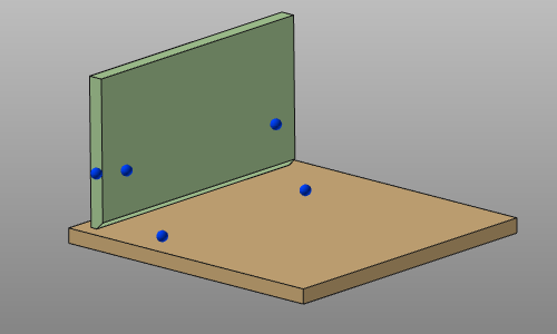
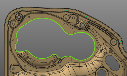
After confirmation the process geometry is computed and displayed and can be recognized by several colored markers.
| Process geometry markers | ||
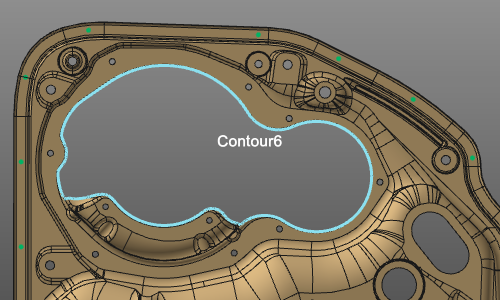
 | The selected contour elements for the process geometry are colored in light blue. | |
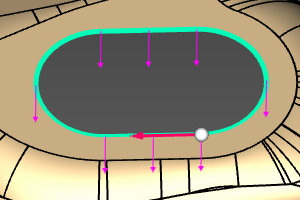
| A white ball with red arrow, indicating the start position of the contour and its direction (for search). | ||
| Purple arrows propagated over the contour elements, indicating the normal vector on the contour. | ||
| When a normal vector is picked a white 3D arrow appears to indicate this normal vector will be edited. The white ball is also placed on this normal vector. |
The normal vector on the contour can point in two directions, of which one would be the ‘positive’ normal direction. But not always this positive normal direction is that obvious to determine. The application therefore supports two methods to define this normal direction, that might give different results.
| Workpiece Preparation workbench Determination of the normal vector on the contour refers to the workpiece origin. | 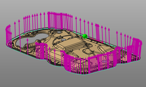 | |
| OLP workbench Determination of the normal vector on the contour refers to the active base frame of the program setup. | 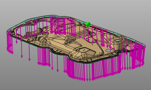 |
From here the process geometry creation can be completed. On the white normal vector a pie menu can be opened.

There is a keyboard short cut for the confirmation. The default is the ENTER key, but this short cut can be changed in the keyboard settings.
Then the contour based process geometry has been created.
When hovering over the process geometry, its name is being displayed.
When the contour can be interpreted as some sort of primitive, regular shape, like a rectangle, circle, etc., the process geometry creation will recognize that. At computation the process geometry will be included with a frame in the center of the shape. A text will be displayed what shape has been detected. The regular shape recognition will only be applied when the option has been activated in the settings of the contour search.
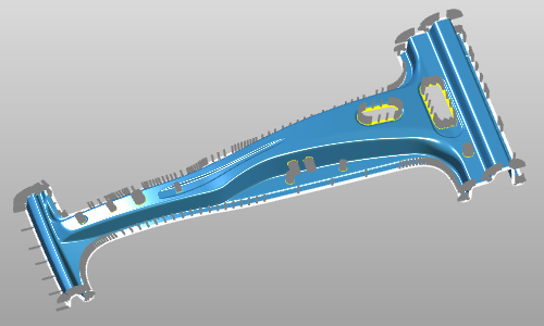
Surface boundary
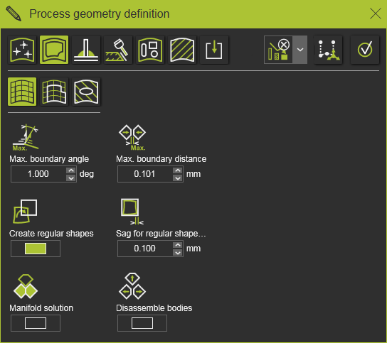
Picking a surface element starts the Surface boundary search functionality. Its purpose is to find all boundary contours on that surface, both the inner and outer ones. The result so far immediate is being displayed.
The surface selection can be extended or reduced with use of the ![]() key.
key.
On the selected surface(s) a pie can be called that includes some additional functions for the boundary contour(s).

There is a keyboard short cut for the confirmation. The default is the ENTER key, but this short cut can be changed in the keyboard settings.
The result process geometry has been given some additional attributes that apply when programming a toolpath on it. These attributes are displayed and can be modified in the table of the process geometry dashboard.
In combination with the arc weld seam definition, these seam attributes are displayed.

Edit the contour process geometry
An existing contour process geometry object always can be modified, but only if the corresponding process geometry command has been started. Then the Edit Pie menu can be opened on a process geometry object when hoovering over that object.

Arc welding seam detection
While defining the welding contour it is possible to include the definition of touch points that are being used for the detection and calibration of the welding seam.