Spraying
Spraying
![]()
Spraying
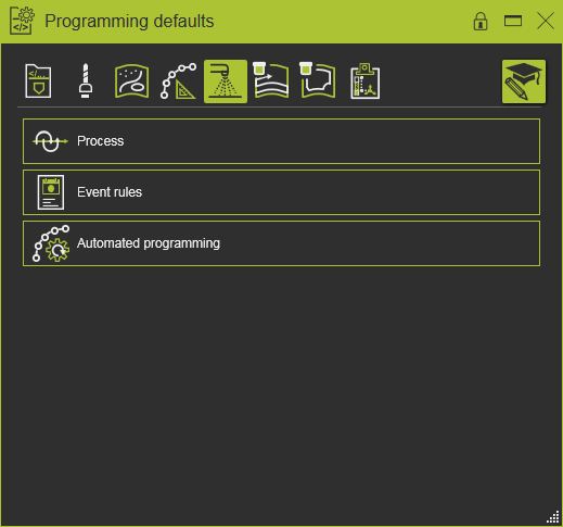
Programming attributes
The display of the programming attributes in the Programming defaults and Active program dashboards is defined in a Settings.xml file. With a standard installation, a default file is located at the path <install>\E2Plugin\Technologies\SprayingTechnology\Standard\ControllerSettings. Specifc spraying technology content of the attributes can be found at the path <install>\E2Plugin\Technologies\SprayingTechnology\Standard\TechTabs.
The following generic attributes have been defined.
| Tech tab | Container | Attribute | Description |
|---|---|---|---|
| At software delivery and standard installation, a default file with brush definitions is located at the path <install>\E2Plugin\Technologies\SprayingTechnology\Standard\TechTabs. | |||
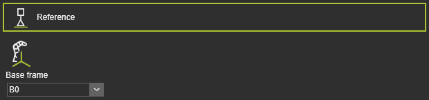 | The program reference information. |
| Base frame | The reference frame of the program. |
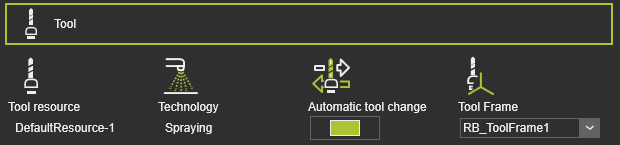 | Tool information. |
| Tool resource | The name of the tool. |
| Technology | The applied technology. |
| Automatic tool change | |
| Tool frame | The tool frame that runs the toolpath. |
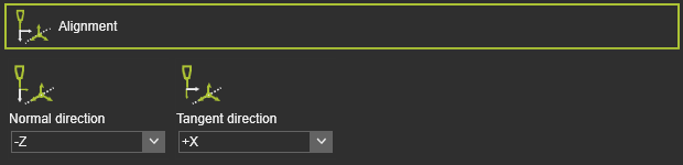 | The mapping of the tool frame axes with the corresponding vectors on the process geometry. |
| Normal direction | The alignment of the tool frame Z axis with the normal direction of the process geometry. |
| Tangent direction | The alignment of the tool frame X axis with the tangent direction of the process geometry. |
| The global transformation of the manufacturing geometry. | |
| Translation in X,Y,Z | The global translation in X,Y or Z direction. |
| Rotation around X,Y,Z | The global rotation around the X,Y or Z axis. |
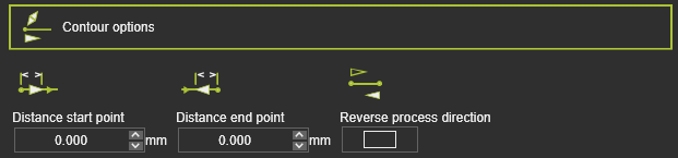 | The boundary conditions on the manufacturing geometry to calculate the toolpath. |
| Distance start point | The distance of the first in-process point from the process geometry start position. |
| Distance end point | The distance of the last in-process point to the process geometry end position. |
| Reverse process direction | To reverse the manufacturing process direction, i.e. changes start to end position and vice verse. |
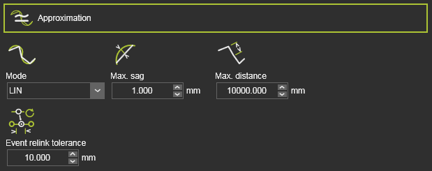 | The approximation of the manufacturing contour to calculate the toolpath. |
| Mode | The mode to approximate the contour. |
| Max. sag | The maximum allowed deviation between the geometry and calculated toolpath. |
| Max. distance | The maximum distance between two in-process toolpath elements along the contour. |
| Event relink tolerance | The tolerance to find the nearest TPE after a toolpath re-computation, to assign the existing event to. This attribute is hidden by default. |
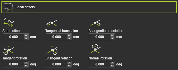 | The offset of the toolpath element from its original location on the manufacturing geometry. |
| Sheet offset | The offset in (surface) normal direction. |
| Tangential translation | The offset of a toolpath element in its tangent direction. |
| Bitangential translation | The offset of a toolpath element in its bi-tangent direction. |
| Tangent rotation | The rotation of the toolpath element round its tangent vector. |
| Bitangent rotation | The rotation of the toolpath element round its bi-tangent vector. |
| Normal rotation | The rotation of the toolpath element round its normal vector. |
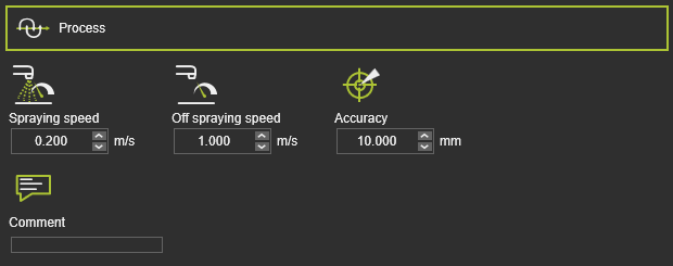 | The motion of the spray nozzle. |
| Spraying speed | The velocity along the in-process spraying path. |
| Off spraying speed | The velocity along the off-process path. |
| Accuracy | The motion accuracy on the toolpath path. |
| Comment | A text comment. |
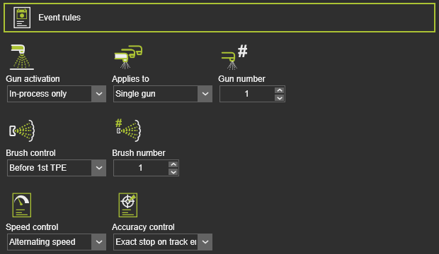 | The events to activate the spray nozzle. |
| Gun activation | The rule when to activate the spraying gun. |
| Applies to | The activation rule will be applied to a single gun or all present guns. |
| Gun number | In case of a single gun activation, the gun that will be activated. |
| Brush control | The rule where to activate the brush. |
| Brush number | The brush number that will be applied. |
| Speed control | The rule to set the velocity along the toolpath. |
| Accuracy control | The rule to set the accuracy along the toolpath. |
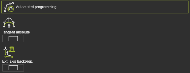 | Additional (optimization) conditions to calculate the toolpath. |
| Tangent absolute | A switch to automatically apply a tangent absolute direction on the in-process path of the operation. The tangent direction of the first in-process point will be used as reference. |
| Ext. axis backprog. | The axis values of an external resource, like a positioner, as been set at the first position of the in-process path, will be propagated backwards up to the approach of that in-process path. |
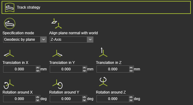 | The strategy to compute the tracks of the toolpath. |
| Specification mode | The mode to compute the tracks. |
| Align plane normal with world | The alignment of the intersecting plane. |
| Translation in X,Y,Z | The global displacement of intersecting plane in X, Y or Z direction. |
| Rotation around X,Y,Z | The global rotation of the intersecting plane round the X,Y or Z axis. |
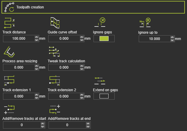 | The actual displayed toolpath creation attributes depend on the applied track strategy. |
| Track distance | |
| Guide curve offset | The offset of the track from the guide curve. |
| Ignore gaps | Switch to ignore gaps that are found in the manufacturing geometry. |
| Ignore up to | The maximum length of the gap that is being ignored. The length is measured along the toolpath for each track individually. |
| Process area resizing | The extension of the process area. |
| Tweak track calculation | The tweak, the deformation of the track to remain parallel. |
| Extend on gaps | The extension of tracks is applied also at gaps in the manufacturing geometry. |
| Track extension 1 | The extension of the track to overrun the process area at the initial side. |
| Track extension 2 | The extension of the track to overrun the process area at the opposite side. |
| Add / remove tracks at start | To duplicate or remove tracks at the start track of the toolpath. A positive value adds a number of copies of tracks, a negative value removes the number of tracks. |
| Add / remove tracks at end | To duplicate or remove tracks at the end track of the toolpath. A positive value adds a number of copies of tracks, a negative value removes the number of tracks. |
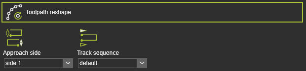 | The starting location of the toolpath. |
| Approach side | The side on the process area where to approach. |
| Track sequence | The sequence of the tracks in default or inverted order. |
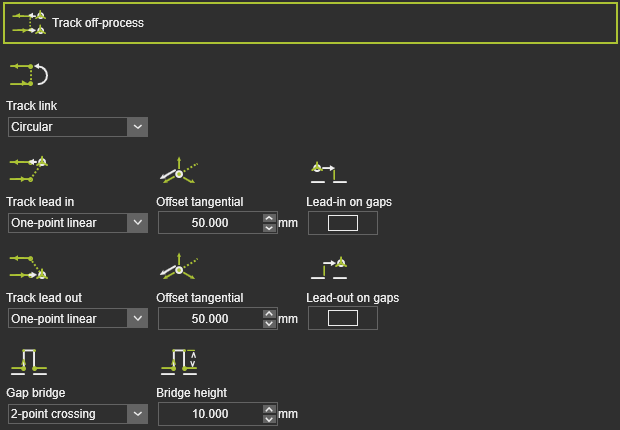 | The off-process conditions of the toolpath. |
| Track link | The cross-over between the individual tracks. |
| Track lead in | The lead in on the track. |
| Offset tangential | The tangential offset of the lead in position. |
| Lead in on gaps | The lead in is applied on gaps that are found in the manufacturing geometry. |
| Track lead out | The lead out from the track. |
| Offset tangential | The tangential offset of the lead out position. |
| Lead out on gaps | The lead out is applied on gaps that are found in the manufacturing geometry. |
| Gap bridge | The bridge definition to cross over gaps. |
| Bridge height | The height of the gap bridge. |
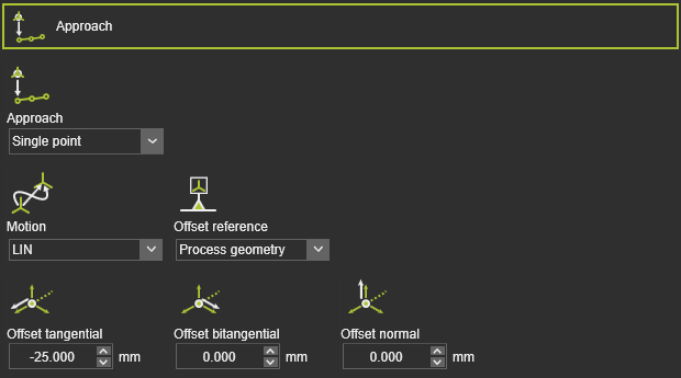 | To define an approach motion towards the in-process toolpath. |
| Approach | The number of approach steps. |
| Motion | The motion type for the approach. |
| Offset reference | The reference to determine the offset directions. |
| Offset tangential / bitangential / normal | The local offset of the approach step from the in-process toolpath start element. |
 | To define a retraction motion away from the in-process toolpath. |
| Retract | The number of retraction steps. |
| Motion | The motion type for the retract. |
| Offset reference | The reference to determine the offset directions. |
| Offset tangential / bitangential / normal | To local offset of the retract step from the in-process toolpath end element. |
| To define an approach motion towards the in-process toolpath. |
| Approach | The number of approach steps. |
| Motion | The motion type for the approach. |
| Offset reference | The reference to determine the offset directions. |
| Offset tangential / bitangential / normal | The local offset of the approach step from the in-process toolpath start element. |
| To define a retraction motion away from the in-process toolpath. |
| Retract | The number of retraction steps. |
| Motion | The motion type for the retract. |
| Offset reference | The reference to determine the offset directions. |
| Offset tangential / bitangential / normal | To local offset of the retract step from the in-process toolpath end element. |
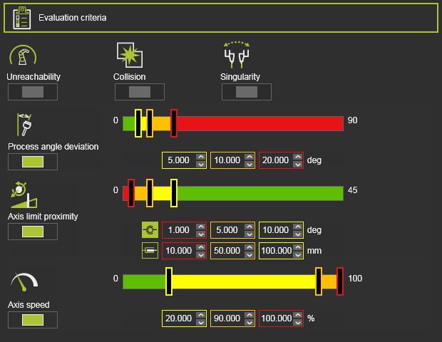 | The toolpath quality evaluation criteria. The exact content may vary per technology. |
| Unreachability | Evaluates unreachable situations of the robot or machine. |
| Collision | Evaluates collision situations. |
| Singularity | Evaluates singularity situations of the robot or machine. |
| Process angle deviation | Evaluates the process angle deviation from its reference value. |
| Axis limit proximity | Evaluates the proximity to the limits of the driven axis. Separated evaluation value range for linear and circular joint axis. |
| Axis speed | Evaluates the axis speed of all driven axis as a (absolute) difference between the start and the end motion between positions. |
Program events
The generic spraying technology has the following programming events:
| Motion events | |
|---|---|
| Sets the velocity for the subsequent motions. | |
| Sets the accuracy for the subsequent motions. | |
| Sets a waiting time at the path element for the tool to remain position until moving further. | |
| Sets the acceleration for the subsequent motions. |
| IO signal events | |
|---|---|
| Adds a wait for an input signal event of the active controller. | |
| Adds a set output signal event of the active controller. | |
| Sets an event to synchronize cooperating robots. | |
| Sets a port of a resource. | |
| Waits for a port of a resource. | |
| Sets a signal of a mechanical parent adapter to create or delete a mechanical connection during simulation. |
| Technology event | |
|---|---|
| Inserts a comment. |
| Activates the spraying gun. | |
| Turns off the spraying gun. | |
| Sets the spraying brush. |
Process simulation models
The spraying technology includes the following process models:
More information
Was this page helpful?