Process simulation
![]()
Process simulation
Process simulation is applying a manufacturing process model during simulation to calculate and visualize the effect of this manufacturing activity. For example the coating thickness of a painting process.
To run a process simulation correctly and reliable some steps have to be taken and boundary conditions are to be set.
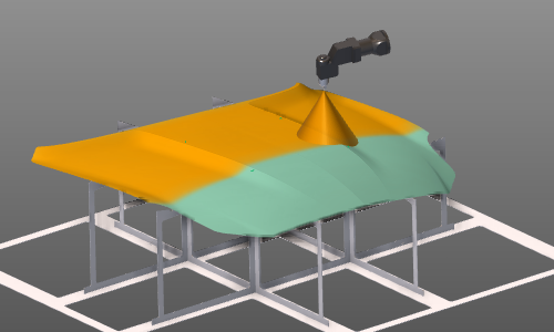
Process simulation object
The process simulation object (PSO) is the component, or part of a component, where the process is impacting on. In other words: the PSO is the object on which the result of a manufacturing process is computed and can be analyzed. In many cases this will be (part of) the workpiece, but also other resources might be impacted by a process.
The PSO is a geometric element, derived from its associated input geometry. A predefined data model determines how this PSO is being generated. This can be different for the various technologies and on what process values will be analyzed. The data model and its attributes can be accessed in the PSO dashboard.
On this data model the effect of the process is calculated during the simulation. The PSO is used to visualize the results of the simulation and to store it with the workpiece.
Process model
The process model is the mathematical model that calculates the values of the manufacturing physical parameters to simulate these parameters. Multiple process models may exist and can work simultaneously. Each of them operates independent from each other.
Although multiple process models may exist, their impact can only be computed on the PSO with a data model that matches with the input data from the process model.
The process model is divided in two parts.
Tool process model
This part of the process model continuously calculates the status and output on the tool during simulation. The information to calculate this status is coming from the tool itself (position, activation, etc.) and from the process controller (for example spray flow rate). With that information, it creates the impact data on the PSO.
The tool process model is activated on the tool resource.
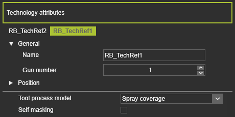
The origin from where the calculation in the 3D space is done is defined as a technology reference frame. This frame will be given a gun number. A tool can have multiple guns and each of them can be activated individually during the offline programming.
When the (tool) resource has been set up for a technology that includes one or more process models, these models will become available in the Resource properties dashboard. The one that is going to be simulated has to be set here.
To calculate the status and output on the tool during simulation, background information is needed.
On one side this needed information is the tool process behavior. This is a data set of information that describes the outcome of the tool under certain defined conditions. For example collected from some experimental data.
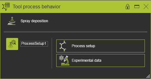
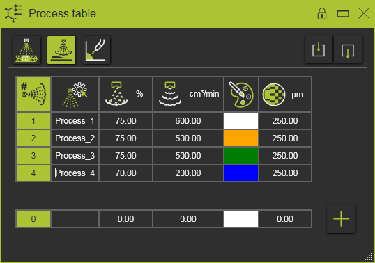
And on the other side this information is the actual state in which the tool is operating during simulation. This can be for example the information at what positions during the simulation the tool is operating. The information is coming from the controller. Besides the signals of when the tool is activated, the controller uses process tables that define the operating conditions of the tool, i.e. the output state of the tool.
The real output of the tool then is calculated and interpolated from the above information.
Object process model
This part of the process model calculates the impact coming from the tool process model on the defined physical parameters of the PSO.
It is very well possible that different process models use the same physical parameter on the PSO.
Simulation
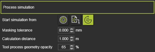
The process simulation has to be activated in the Simulation player bar.
In the Simulation Settings, the boundary conditions for the process simulation are defined.
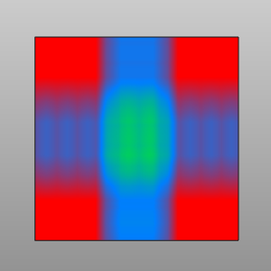
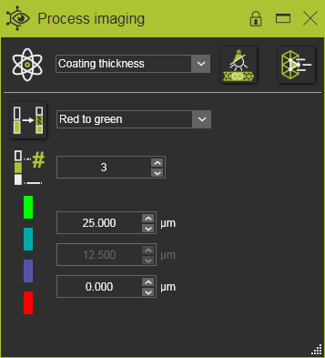
Imaging
The simulation result is directly visualized on the PSO. The Process imaging dashboard offers several post-processing tools to display the simulation result in a preferred manner to be able to analyze it.
The actual result and with that its accuracy, of a process simulation that is displayed depends on the combination of the tool motion, the size of the elements of the process geometry object and the simulation step speed. With that in perspective, the simulation may show smaller deviations locally and graphical output what is know as moiré effects.