Toolpath
![]()
Toolpath
A toolpath is the base information to describe the motion of the tool center point (TCP) of the manufacturing resource. It consists of a series of individual, single moves to predefined (target) locations. The attributes to determine the move are inherited from the previous move or are locally specified by commands or events.
Each of these path moves is represented by a toolpath element (TPE) that is defined by
-
a tag: the location with respect to the base frame of the OLP project
-
a target type: Cartesian or joint target definition
-
a motion type: the type of path how to move to the location.
The toolpath is the resulting data object of the computation of these path moves. It is the data base for the visualization and manual modification during programming, internal simulation and for the controller neutral download file.
Motion types
| PTP | A Point to Point motion, also called synchronized PTP, is defined by the resource joint axes position at position A and B of the tool path. During the travel of the TCP, all resource joint axes start to move in point A and stop moving at point B, and therefore move simultaneously in time. Thus the slowest axis, or the one with the longest travel, determines the motion time of the TCP. The PTP motion does not make use of any intermediate control points on the tool path between point A and B and therefore the actual motion of the TCP is unpredictable and not necessarily following the computed tool path. |
| Linear | A linear motion is defined in such way that the TCP travels along a straight line between point A and B, with the condition that it moves with a constant speed (feedrate). Each path (between point A and B) has to be regenerated into segments with intermediate control points, including the information about Cartesian speed, acceleration, tool path shape (line, circular arc, polynomial, etc.). Because of that, the linear motion significantly requires more computation resources than the PTP motion. |
| Circular | The circular motion is from systematic comparable with the linear motion. Three support points define a plane in which the circular arc is calculated. The normal vector will be directed normal to this plane. The restriction for circular motion is that the start and end point cannot be the same: it would fail to build the circular arc. |
Toolpath types
The toolpath can be generated on three type of (geometrical) objects:
-
point based: the toolpath is computed based on the tags
-
contour based: the toolpath is computed on a curve object, taken into account a segmentation fault, maximum distance and forced supports
-
surface based: the toolpath is computed as a set of connected parallel contours lying on the surface.
Point based
Point based process geometry generates a tool path operation position at each of the selected process geometry points.
Contour based
The contour process geometry will be approximated when the tool path is generated. The method and accuracy of the approximation is defined in the Programming defaults. When generating the tool path, a tag will be created at each approximation limit connected with a path direction line.
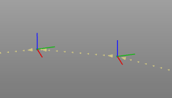
When a circular approximation is applied, an additional tool path element is created in the middle of each approximated arc segment. This tool path element is called a via point, and is recognized as dotted axis.
Depending on the chosen technology and program settings, additional information, such as approach and retract positions and event flags, might be generated together with the selection.
Surface based
Starting from a guiding curve (intersection or boundary), the surface is represented by a set of contours, i.e. tracks that are parallel to this guiding curve. These tracks then are connected to build one continuous path.
Toolpath visualization
After computation the tool path is displayed. In the Display Filter some options are available of what information is actually shown.
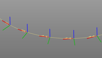
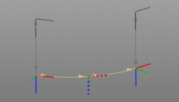
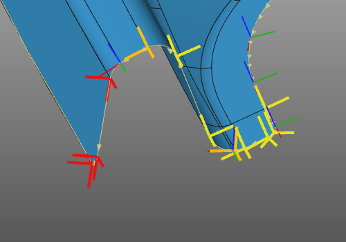
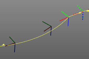
The tool path is visualized by its the tag positions, represented by axis systems, and by the paths that connect the tags.
The blue axis of the TPE represents the normal direction and the red axis the tangent direction.
The paths are displayed in different colors for the in-process and off-process section and with different symbols to indicate the motion type.
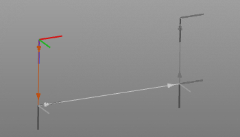 |  |  | ||
| Approach | Path | Retract |
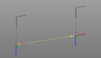
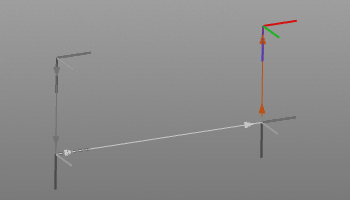
| 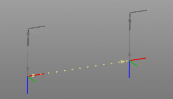 |  | ||
| Linear motion | PTP motion | Circular motion |
A circular motion has a mid point on the circular arc, a so called via point. This is an additional toolpath element that can be manipulated also.
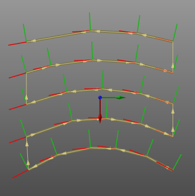
The parallel curve toolpath, usually applied on a surface, can visually be divided into the parallel tracks, the track lead-in and lead-out and their connection.
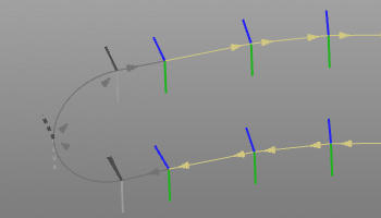 | 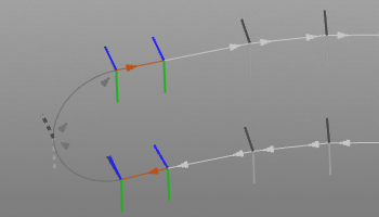 | 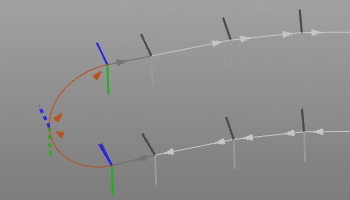 | ||
| Parallel tracks | Lead-in / -out | Track link |
Furthermore there are many different options how to display a toolpath and its single positions. The majority of these options are to be set in the Display filters.
Quality evaluation
With the creation and modification of a tool path, a quality evaluation is performed automatically. The evaluation is run against several predefined criteria.
The resulting incidents of the evaluation are displayed in several dashboards and on the 3D toolpath.
Suppressed
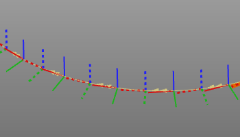
At creation of the toolpath, each individual element (TPE) has become an active member of that path. However, it is possible to ignore these elements afterward for simulation or downloading, without deleting them. That is so called to suppress such element.
When a TPE is suppressed, its display color turns dark and the toolpath is recomputed automatically.
Toolpath modification
Changes that are made to the toolpath in many cases require a full recomputation of that toolpath.
The recomputation of the toolpath, i.e. program, can be set to be executed automatically. In this case the program will be recomputed after each modification. To collect changes and then execute the update, the manual recomputation can be set in the Settings. In that case a recomputation command button appears in the top left corner of the 3D space to indicate if a recomputation is required or not.
 |  | |
| No recomputation required | Recomputation required |