Workpiece properties
![]()
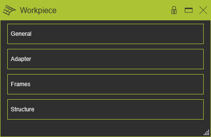
Dashboard
The Workpiece command opens the controller dashboard. In this dashboard the properties and attributes of the controller can be verified and modified when needed. The dashboard has three containers that can be opened or closed by clicking inside the tab’s frame.
General
This container opens the general information of the workpiece.
The workpiece has the following general attributes. At creation of the workpiece the default values for the attributes are given by the software. The attributes are shown and editable in the dashboard function of the Workpiece Preparation Workbench.
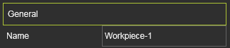
The General container opens with a vertical list with all the defined attributes within the component.
| Attribute | Description | Remark |
|---|---|---|
| Name | The name of the workpiece | A name for the workpiece is mandatory. |
Adapter
This container opens the adapter information of the workpiece. The editor shows the individual adapters and their definition.Selecting an adapter will cross highlight it in the 3D View and its name in the list.
The adapter has the following base attributes. At creation of the adapter the default values for the attributes are given by the software, depending on the choice of type of adapter.The attributes are shown and editable in one of the dashboard functions of the different Workbenches that support the creation of adapters.
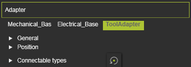
The Adapter container opens with a vertical list with all the defined attributes within the component, shown by their names. Selecting one of them will show its attributes sorted in two groups. A cross highlighting in the 3D View and the dashboard UI appears.
| Attribute | Description | Remark |
|---|---|---|
| Name | The name of the adapter. | A blank name is allowed. |
| Type | The type of the adapter according to the classification. 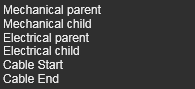 | |
| Capacity | Defines how many adapters can be connected to this one. | Applies only to socket type adapters. |
| X, Y, Z | The X,Y and Z coordinates of the adapter. | Coordinates are set to the component’s global coordinate system. |
| Roll(X), Pitch(Y), Yaw(Z) | The roll, pitch and yaw orientation of the adapter. | Orientation angles are set to the component’s global coordinate system. |
| Defines which classes of components can plug in to this adapter. Selection through the corresponding class icon. | Applies only to mechanical socket adapters. The Reset command switches the definition back to the base setup | |
The resource classes. 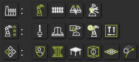 | Picking the category icon sets all components of the category. | |
| The classes humans, controller and workpiece. |
Frames
This container opens the frame information of the workpiece. The editor shows the individual frames and their definition.Selecting a frame will cross highlight it in the 3D View and its name in the list.
The frame has the following base attributes. At creation of the frame the default values for the attributes are given by the software, depending on the choice of type of frame.The attributes are shown and editable in one of the dashboard functions of the different Workbenches that support the creation of frames.
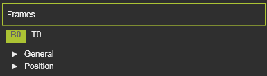
The Frames container opens with a vertical list with all the defined attributes within the component, shown by their names. Selecting one of them will show its attributes sorted in two groups. A cross highlighting in the 3D View and the dashboard UI appears.
| Attribute | Description | Remark |
|---|---|---|
| Name | The name of the frame. | A blank name is allowed. |
| Type | The type of the frame according to the classification as described above. | |
| Vision frame | The frame will be assigned as additional tool reference. | Applies to (resource) tool frames only. Vision frames are used in different applications, technologies or functions for dedicated solutions, like the arc welding seam calibration. |
| X, Y, Z | The X,Y and Z coordinates of the frame. | Coordinates are set to the component’s global coordinate system. |
| Roll(X), Pitch(Y), Yaw(Z) | The roll, pitch and yaw orientation of the frame. | Orientation angles are set to the component’s global coordinate system. |
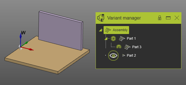
Structure
This container is only available when the workpiece is a union workpiece. It shows the hierarchy structure of the union, as in the example below.
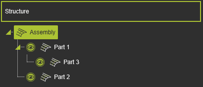
With the toggle markers the tree can be expanded or collapsed.
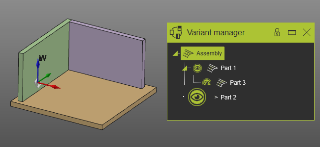
Each individual node in this hierarchy has an option to be visualized or not. The symbol in front of the workpiece node enables to switch the visualization on or off.
 |  | |
| Visualization on | Visualization off |
The node visualization should not be confused with the Show / Hide state of an object. In the last case the object is moved to the Show or Hide workspace. The node visualization does not do this. Within the union workpiece it enables to display each individual node of the union.
On each node the Pie menu can be opened to disassemble a child workpiece from its parent.