Generic technology
Generic technology
![]()
Generic operation
The generic technology is a basic package to program a toolpath for point, contour or surface based operations.
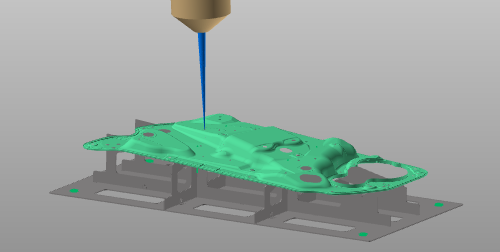
Programming a toolpath here generates a cycle that consist of three sections:
![]()
approach (off-process)
![]()
in-process
![]()
retraction (off-process)
The cycle is calculated and controlled by the programming attributes and events.
Programming attributes
The display of the programming attributes in the Programming defaults and Active program dashboards is defined in a Settings.xml file. With a standard installation, a default file is located at the path <install>\E2Plugin\Technologies\GenericTechnology\Standard\ControllerSettings.
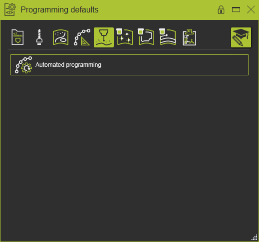
For the generic controller the following attributes have been defined.
| Tech tab | Container | Attribute | Description |
|---|---|---|---|
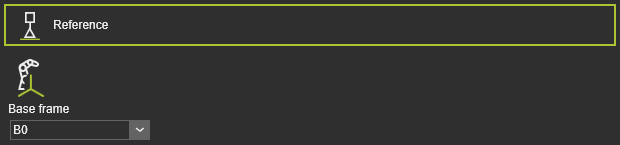 | The program reference information. |
| Base frame | The reference frame of the program. |
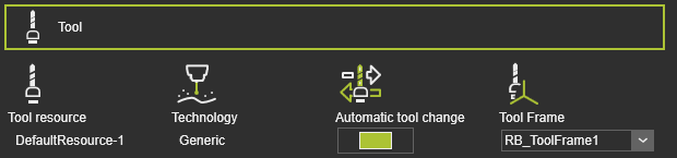 | Tool information. |
| Tool resource | The name of the tool. |
| Technology | The applied technology. |
| Automatic tool change | |
| Tool frame | The tool frame that runs the toolpath. |
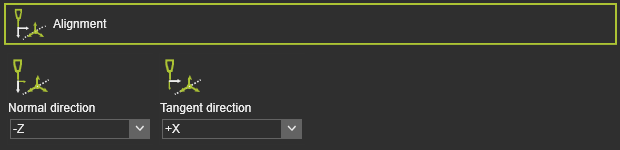 | The mapping of the tool frame axes with the corresponding vectors on the process geometry. |
| Normal direction | The alignment of the tool frame Z axis with the normal direction of the process geometry. |
| Tangent direction | The alignment of the tool frame X axis with the tangent direction of the process geometry. |
| The global transformation of the manufacturing geometry. | |
| Translation in X,Y,Z | The global translation in X,Y or Z direction. |
| Rotation around X,Y,Z | The global rotation around the X,Y or Z axis. |
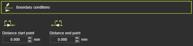 | The boundary conditions on the manufacturing geometry to calculate the toolpath. |
| Distance start point | The distance of the first in-process point from the process geometry start position. |
| Distance end point | The distance of the last in-process point to the process geometry end position. |
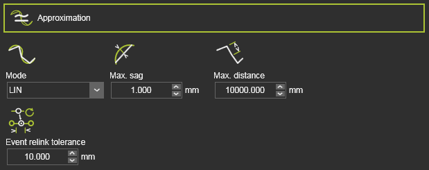 | The approximation of the manufacturing contour to calculate the toolpath. |
| Mode | The mode to approximate the contour. |
| Max. sag | The maximum allowed deviation between the geometry and calculated toolpath. |
| Max. distance | The maximum distance between two in-process toolpath elements along the contour. |
| Event relink tolerance | The tolerance to find the nearest TPE after a toolpath re-computation, to assign the existing event to. This attribute is hidden by default. |
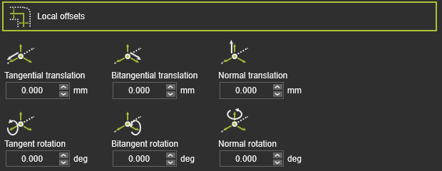 | The offset of the toolpath element from its original location on the manufacturing geometry. |
| Tangential translation | The offset of a toolpath element in its tangent direction. |
| Bitangential translation | The offset of a toolpath element in its bi-tangent direction. |
| Normal translation | The offset of a toolpath element in its normal direction. |
| Tangent rotation | The rotation of the toolpath element round its tangent vector |
| Bitangent rotation | The rotation of the toolpath element round its bi-tangent vector. |
| Normal rotation | The rotation of the toolpath element round its normal vector. |
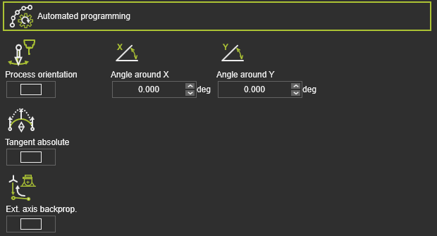 | Additional (optimization) conditions to calculate the toolpath. |
| Process orientation | A switch to optimize each toolpath element with use of the positioner axis to maintain the tool axes in down-hand direction. The condition is only available when a 1-2 axis positioner, carrying the workpiece, is connected to the controller. |
| Tangent absolute | A switch to automatically apply a tangent absolute direction on the in-process path of the operation. The tangent direction of the first in-process point will be used as reference. |
| Ext. axis backprog. | The axis values of an external resource, like a positioner, as been set at the first position of the in-process path, will be propagated backwards up to the approach of that in-process path. |
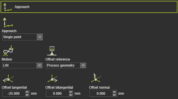 | To define an approach motion towards the in-process toolpath. |
| Approach | The number of approach steps. |
| Motion | The motion type for the approach. |
| Offset reference | The reference to determine the offset directions. |
| Offset tangential / bitangential / normal | The local offset of the approach step from the in-process toolpath start element. |
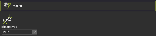 | The motion definition. |
| Motion | The motion type for the tool head. |
 | To define a retraction motion away from the in-process toolpath. |
| Retract | The number of retraction steps. |
| Motion | The motion type for the retract. |
| Offset reference | The reference to determine the offset directions. |
| Offset tangential / bitangential / normal | To local offset of the retract step from the in-process toolpath end element. |
| To define an approach motion towards the in-process toolpath. |
| Approach | The number of approach steps. |
| Motion | The motion type for the approach. |
| Offset reference | The reference to determine the offset directions. |
| Offset tangential / bitangential / normal | The local offset of the approach step from the in-process toolpath start element. |
| To define a retraction motion away from the in-process toolpath. |
| Retract | The number of retraction steps. |
| Motion | The motion type for the retract. |
| Offset reference | The reference to determine the offset directions. |
| Offset tangential / bitangential / normal | To local offset of the retract step from the in-process toolpath end element. |
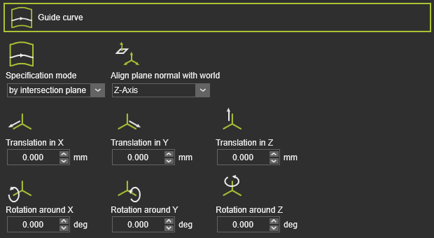 | The base curve to define orientation and direction of the toolpath tracks. |
| Specification mode | The mode to define the guide curve. |
| Align plane normal with world | The alignment of the guide curve intersecting plane. |
| Translation in X,Y,Z | The global displacement of the guide curve in X, Y or Z direction. |
| Rotation around X,Y,Z | The global rotation of the guide curve around the X,Y or Z axis. |
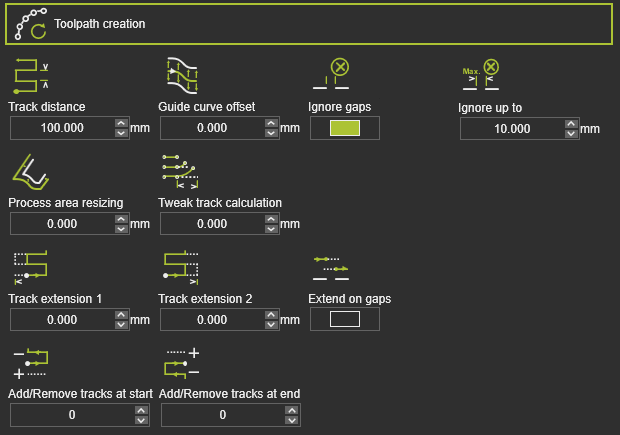 | The actual displayed toolpath creation attributes depend on the applied track strategy. |
| Track distance | |
| Guide curve offset | The offset of the track from the guide curve. |
| Ignore gaps | Switch to ignore gaps that are found in the manufacturing geometry. |
| Ignore up to | The maximum length of the gap that is being ignored. The length is measured along the toolpath for each track individually. |
| Process area resizing | The extension of the process area. |
| Tweak track calculation | The tweak, the deformation of the track to remain parallel. |
| Extend on gaps | The extension of tracks is applied also at gaps in the manufacturing geometry. |
| Track extension 1 | The extension of the track to overrun the process area at the initial side. |
| Track extension 2 | The extension of the track to overrun the process area at the opposite side. |
| Add / remove tracks at start | To duplicate or remove tracks at the start track of the toolpath. A positive value adds a number of copies of tracks, a negative value removes the number of tracks. |
| Add / remove tracks at end | To duplicate or remove tracks at the end track of the toolpath. A positive value adds a number of copies of tracks, a negative value removes the number of tracks. |
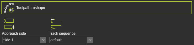 | The starting location of the toolpath. |
| Approach side | The side on the process area where to approach. |
| Track sequence | The sequence of the tracks in default or inverted order. |
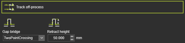 | The off-process conditions of the toolpath. |
| Gap bridge | The bridge definition to cross over gaps. |
| Retract height | The height of the gap bridge. |
| To define an approach motion towards the in-process toolpath. |
| Approach | The number of approach steps. |
| Motion | The motion type for the approach. |
| Offset reference | The reference to determine the offset directions. |
| Offset tangential / bitangential / normal | The local offset of the approach step from the in-process toolpath start element. |
| To define a retraction motion away from the in-process toolpath. |
| Retract | The number of retraction steps. |
| Motion | The motion type for the retract. |
| Offset reference | The reference to determine the offset directions. |
| Offset tangential / bitangential / normal | To local offset of the retract step from the in-process toolpath end element. |
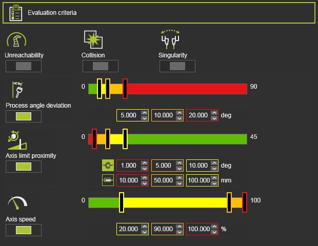 | The toolpath quality evaluation criteria. The exact content may vary per technology. |
| Unreachability | Evaluates unreachable situations of the robot or machine. |
| Collision | Evaluates collision situations. |
| Singularity | Evaluates singularity situations of the robot or machine. |
| Process angle deviation | Evaluates the process angle deviation from its reference value. |
| Axis limit proximity | Evaluates the proximity to the limits of the driven axis. Separated evaluation value range for linear and circular joint axis. |
| Axis speed | Evaluates the axis speed of all driven axis as a (absolute) difference between the start and the end motion between positions. |
Program events
The generic technology has the following programming events:
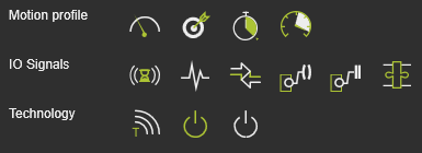
| Motion events | |
|---|---|
| Sets the velocity for the subsequent motions. | |
| Sets the accuracy for the subsequent motions. | |
| Sets a waiting time at the path element for the tool to remain position until moving further. | |
| Sets the acceleration for the subsequent motions. |
| IO signal events | |
|---|---|
| Adds a wait for an input signal event of the active controller. | |
| Adds a set output signal event of the active controller. | |
| Sets an event to synchronize cooperating robots. | |
| Sets a port of a resource. | |
| Waits for a port of a resource. | |
| Sets a signal of a mechanical parent adapter to create or delete a mechanical connection during simulation. |
| Technology event | |
|---|---|
| Inserts a comment. |
| Activates the tool. | |
| Stops the tool activity. | |
More information
Was this page helpful?