3 Point calibration
![]()
Calibration
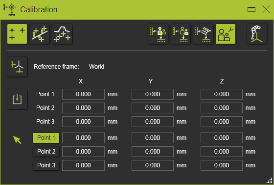
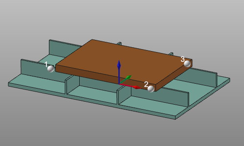
Three point calibration is used to correctly position a workpiece or a resource, e.g. a fixture, in the virtual workcell. The calibration is based upon an exact mathematical method of having 3 static points on the component that can be measured on the real part and can be selected on the corresponding virtual part. The method will bring the two sets of points into congruence and as such will move the component along with that.
Reference frame
![]()
The Reference frame button is an option to specify the reference coordinate system (calibration reference frame) in which the measured points are being imported. By default the World coordinate system is used.
Import
![]()
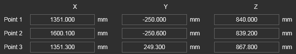
The input for the calibration is a set of three measured coordinates. These coordinates usually are imported from an external file, but manual entering or modifying these values is possible.
The input file with the measured points is a simple text file that is read line by line. It has an optional first line with the unit indicator, followed by three lines of coordinates. Coordinate lines have to contain exactly three coordinate values, separated by semicolon. Each line is interpreted as the X, Y and Z coordinates of a single point. By default these points are imported in the 3D space world coordinate system, but another reference coordinate system can be defined in the dashboard. An example of such import file is shown below.
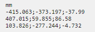
The unit of the coordinates is specified in the first line of the file. Any unit, known by the software can be applied here. It can be written in full name or as the standard abbreviation of that unit. When however the unit line is missing in the file, the import will read the coordinates with the system default unit.
The decimal sign of the coordinate is language and region settings independent. It always has to be a point ”.”.
Although the unit in the import file has been specified, the dashboard will display the coordinates according the current system units. The values then are converted when needed.
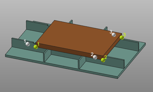
With the Import button the measured data of the object’s position in the real workcell is read. A file browser appears to select the data file. The measured coordinates are displayed as white spheres in the 3D space. This default color can be changed in the Settings.
The result of the import is displayed in the reference section of the dashboard. The coordinate values of the measured positions can be modified here when necessary.
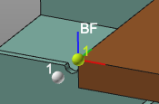
Selected points
![]()
Here the selected points of the component are displayed. These calibration points directly can be selected on the workpiece or resource.They are displayed as green spheres. This default color can be changed in the Settings.
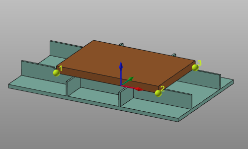
At any time a point can be set active by picking the 3D representation or by clicking the item in the dashboard. Then a new point can be selected or its coordinates can be altered in the dashboard.
Compute
The calibration result is computed immediately after all steps have been completed.
The dashboard however stays open. It allows to change anything at the input and to have the calibration recomputed on the fly. Closing the dashboard or starting any other command terminates the calibration with the last computed solution.
Calibration result option
The result of the calibration is a transformation of the component. The way it will be applied can be defined in the result options.
| Initial situation. | 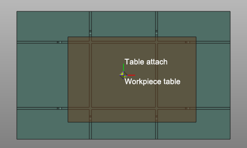 | ||
| Create a new child adapter | In the root of the calibrated component a new mechanical child adapter will be created; CalibPlug. The component itself is not transformed. The new adapter can be used to reposition the component according the calibration coordinates. | 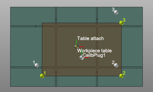 | |
| For the following result options, the component has to be attached to another one; for example a workpiece on a table. The child adapter of the to be calibrated component has been connected to the parent adapter of the other component. | |||
| Define the transformation | The component will be moved into the calibrated position, but the adapters are not changed. There will be an offset between the two connected components. A connection line between the two adapters is displayed. | 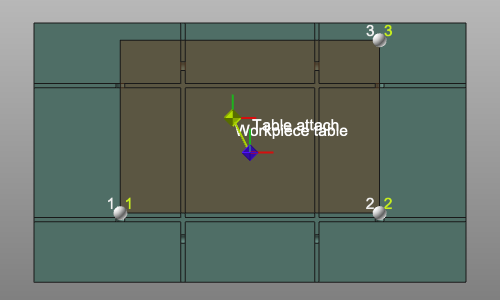 | |
| Move the child adapter | The component is moved to the calibrated position. Its child adapter is moved along with the transformation. This generates a modification of the component definition. It therefore needs to be saved again. | 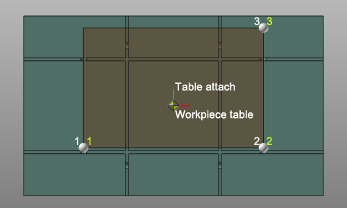 | |
| Move the parent adapter | The component is moved to the calibrated position. The parent adapter of the connected component is moved along with the transformation. This generates a modification of that connected component definition. It therefore needs to be saved again. | 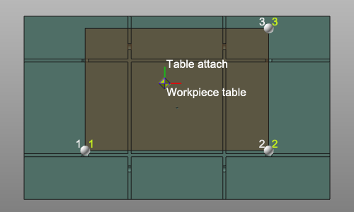 |
![]()
The Create base frame option is a switch to create an additional base frame at the first selected point.