Layout properties
![]()
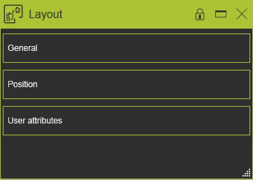
The Layout dashboard shows the properties and attributes of the layout.
General
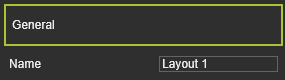
In this container the general properties and attributes of the layout are placed.
| Attribute | Description | Remark |
|---|---|---|
| Name | The name of the layout | Can be edited. The value can be empty. |
Position
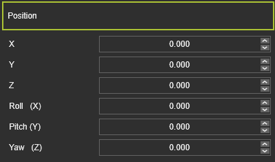
In this container the position of the layout in the 3D world can be modified.
| Attribute | Description | Remark |
|---|---|---|
| X, Y, Z | The X, Y and Z coordinates of the layout’s origin. | Coordinates are set to the global coordinate system. |
| Roll(X), Pitch(Y), Yaw(Z) | The roll, pitch and yaw orientation of the layout’s origin. | Coordinates are set to the global coordinate system. |
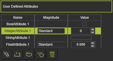
User attributes
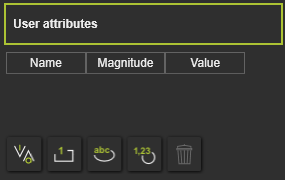
This container opens the user defined attributes of the layout. The editor shows the attributes and their definition. User defined attributes can be added, modified and deleted here.
There are four main types of use defined attributes.
| Type | Description | Remark | |
|---|---|---|---|
| Boolean | An attribute that has either the value True or False. | The value is set True by pressing the value button | |
| Integer | An integer number of different magnitudes. For each magnitude the unit is set and displayed automatically. | A drop down list is available to specify the required magnitude 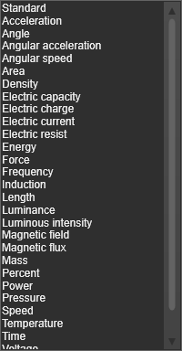 | |
| String | A text based attribute. | ||
| Float | A real number of different magnitudes. For each magnitude the unit is set and displayed automatically. | A drop down list, same as for the integer attribute, is available to specify the specific magnitude. |
The user defined attribute can be added by clicking on the attribute type button. The attribute will be added to the list and is given a default name and value. Selecting the name or value enables to modify it.
The currently active, selected, user defined attribute can be removed by pressing the
Deletecommand button
![]()
.
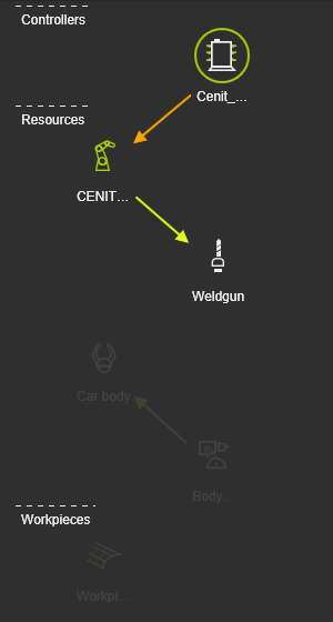
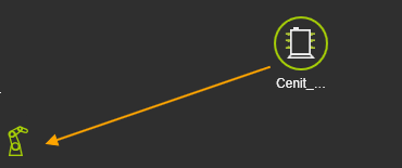
The diagram container displays the layout structure with its components, divided in blocks of their type, starting with the controllers on top as being the manager of the layout. Colored arrows indicate a connection: yellow/green representing the mechanical connection, orange the electrical. Both connection indicators can be shown or switched off with the check box located at the bottom of the diagram.
The layout block diagram has only a visualization purpose. Hoovering over a component symbol in the diagram cross-highlights it in the 3D View. Picking a component displays only the component itself and its relations in the diagram, the other components in the diagram are dimmed. Picking in the background resets the diagram to full image again.
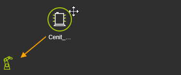
For a better overview it is possible to reorder the component symbols in the diagram. When a component has been picked, the mouse shows the Move symbol. It then can be dragged to another location in its section of the diagram.
 |  |