Weld seam calibration - touch sensing
![]()
Touch sensing methods
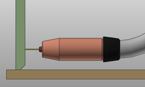
Touch sensing is the calibration method where the welding gun runs into collision with the to be welded parts at a number of pre-defined positions.
Two methods are implemented:
| Method | Description | |
|---|---|---|
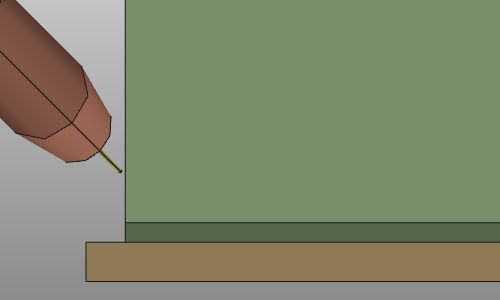
| Touch with wire | The welded part position is determined by the collision between the part and the welding torch wire. Depending on the number of degrees of freedom to be eliminated, a minimum number of touches must be defined. Calibration of the part position is done before starting the welding process. | 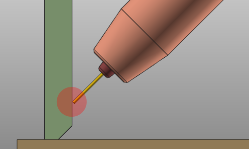 |
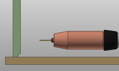
| Touch with nozzle | The welded part position is determined by the collision between the part and the nozzle of the welding torch nozzle. Depending on the number of degrees of freedom to be eliminated, a minimum number of touches must be defined. Calibration of the part position is done before starting the welding process. | 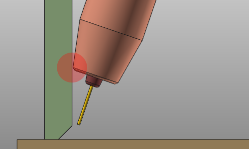 |
The number of points that are needed for touch sensing and the usage of touch with wire or nozzle usually is robot and welding torch vendor specific.
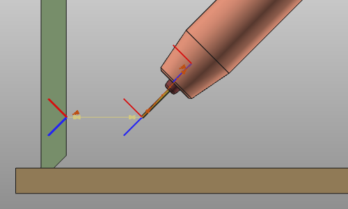
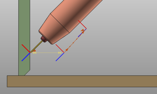
Touch directions
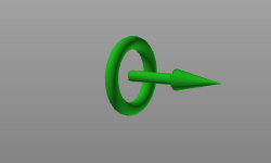
Basically the touch positions can be applied in three directions:
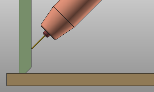 | 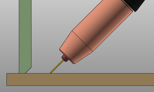 |  | ||
| Work direction | Tool direction | Travel direction |
Operation cycle
The touch operation is a cycle of a fix number of pre-defined positions and motion behavior. The nozzle angles are defined in the programming attributes and are kept the same during the whole touch operation.
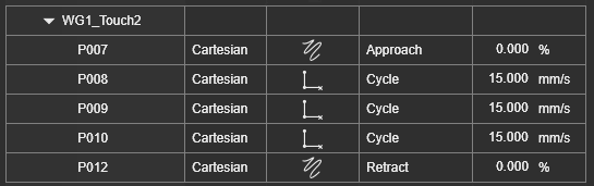
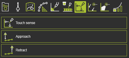
The cycle has the following positions:
| Position | Description | Remark | |
|---|---|---|---|
 | Approach | The approach position from where the touch cycle starts. | Optional. |
 | Start | The start position of the touch cycle. This position is calculated as a linear offset from the theoretical touch point on the surface, measured perpendicular to that surface. | |
 | Touch | The touch position. This position is a linear offset from the theoretical touch point and is determined from the collision of the welding torch with the welding part while moving from the start towards the theoretical position.. 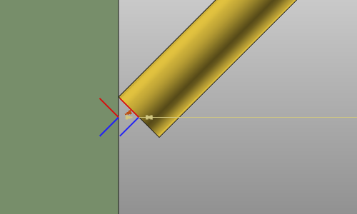 | |
| Return | The return position of the touch cycle. The position is usually the same as the start position | |
| Retract | The retract position from the end of the touch cycle. | Optional. |
When using the touch by wire method, the operation optionally can be extended with a wire check cycle. Before the wire touch is being executed the torch travels to the touch point to verify the presence of the welding wire. The cycle is a simple linear motion between the start and touch position and back.
| Position | Description | |
|---|---|---|
 | Start | The start position of the touch cycle. The welding torch orientation has been set perpendicular to the touched surface. |
 | Check | The (theoretical) touch position, that also is used for the wire check. |
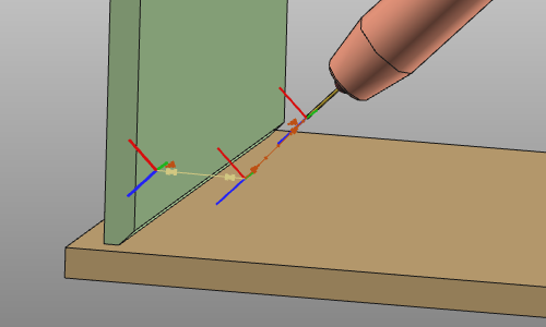
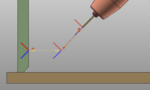
The standard way to display an operation (cycle) is to show the individual toolpath positions by an axis system. The touch cycle however can also be displayed with an alternative graphical representation. Such might be convenient when many toolpath positions with several touch operations have to be displayed.
This representative display can be switch on or off in the Toolpath and operations container of the Display filters.
![]()
With the Show / Hide the operation cycle as representation, the whole touch operation cycle can be displayed with one graphical representation.
Touch attributes
In the Touch sensing tech tab of the Programming defaults the standard touch sensing attributes are available. Other controller manufacturer specific attributes may be displayed too but are not described on this page here.
The Touch sense container includes the following attributes:
| Attribute | Description | Remark | |
|---|---|---|---|
| Detection type | The touch method, i.e. the part of the welding torch that is running into collision to detect the welding part: | ||
| Touch angle adjustment | Additional rotation to adjust the touch angle. | ||
| Start offset from touch | The offset from the theoretical touch position to the start position of the cycle. | ||
| Motion to touch start | The motion to the first position of the touch cycle. | ||
| Sensing speed | The speed during the touch cycle. | ||
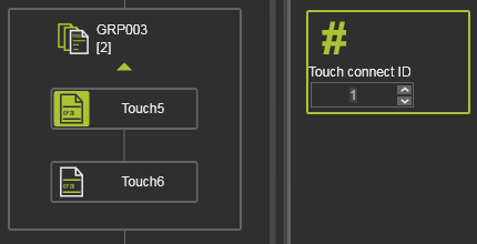
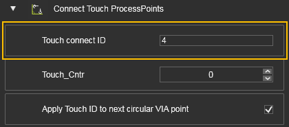
| Touch connect ID | The identifier of the touch cycle and calibration. Defines which welding operations are using which touch calibration. | ||
| Wire check | The option to include an additional wire check cycle before touching. | Only applicable in the wire detection method. |
Connection with welding operation
Touch operations, i.e. seam calibration, and welding operations are related somehow. Each welding operation might have its own calibration, or a calibration is executed for multiple welding operations.
Each touch sensing operation is is given a sequential number; the Touch connect ID. This ID can be verified, or even modified, in the Active program dashboard.
When programming a welding operation with touch sensing, the system automatically generates a connection between both operations. An event is added at the first toolpath position of the welding operation.
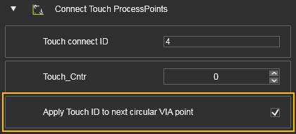
When the operation is a circular path with a via point, the connecting ID can be applied also to this via point. This might be needed when defining the calibration transformation of the welding seam over the connection type attribute.
When programming a welding operation without new touch calibration, the system assigns the last connection ID to the welding operation. In the Event panel, this can be changed when needed.
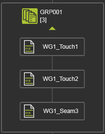
The system groups the welding and touch operations not only over the Connection ID. After initial computation, the operations are also grouped by there name, to visualize their relation. A default name starting with WGx (x = ID number) is given to the operations.
However; it has to be understood that manual changes do not update the Connection ID, nor the connection between welding and touch operations. This has to be verified and corrected manually.
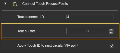
When downloading the program, the system analyzes all the welding and touch operations. The number of touch positions that belong together are collected and written in the event attribute Touch Counter.
Connection types
The touch sensing calibration includes the possibility to define how the touch positions are connected to the welding toolpath.
| Attribute | Description | Remark | |
|---|---|---|---|
| Connection type | Assigning the touch positions to the welding operation toolpath. | Possibilities: 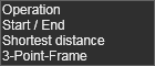 |
Operation
All the defined touch positions are connected to the welding operation as one group with the same ID. The connection event is assigned to the first toolpath position of the welding operation. As a result, the whole welding seam is calibrated with the same transformation.
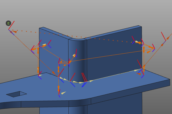
Start / End
An event is assigned to the first position and an event is assigned to the last position of the welding operation. The touched positions are assigned to either the first or the last welding process point. This is simply done based on the shortest distance between these welding positions and the individual touch positions. As a result, the welding seam is calibrated with a transformation at the start and a transformation at the end of the seam.
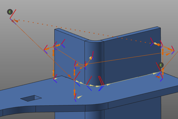
Shortest distance
Each process point of the welding operation gets an event for the touch calibration, with its own connection ID. The touch positions are assigned to the nearest process point. As a result, each toolpath position on the seam is calibrated individually.
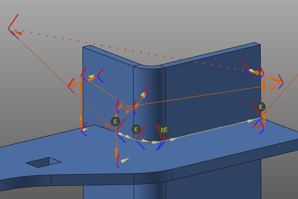
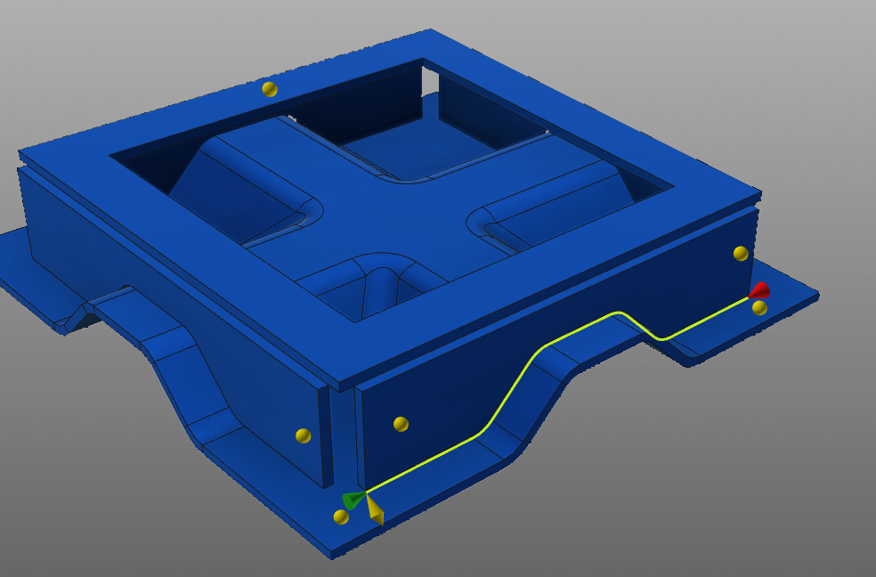
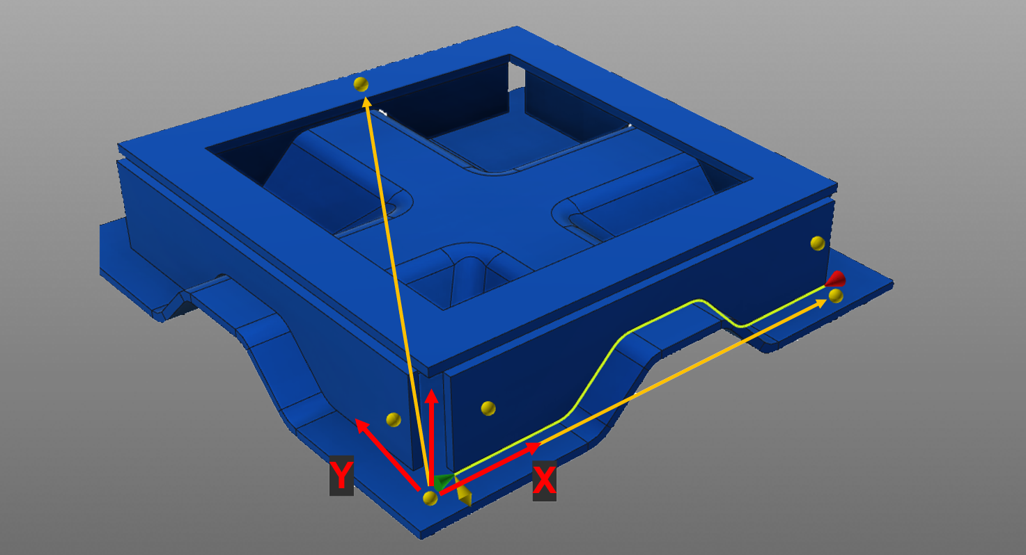
3 Point frame
A calibration frame (coordinate system) is computed from at least 3 and up to 6 touch positions. The touch positions are grouped to be able to place and orient this frame.
The origin of that frame is located in the first touch position. This 1st frame point is associated with either the start or end point of the welding seam, depending on which one is closer. The last touch is assigned to the 3rd frame point which represents a point on the XY-plane of the correction frame. All remaining touches are either assigned to the 1st or the 2nd frame point. The 2nd frame point represents the local X-axis of the correction frame.
The completed frame is later used to correct the welding seam.
The first touched position of the first group is the first frame point and the origin of the frame. This first frame point is associated with either the start or end point of the welding seam, depending on which one of them lies closer to the frame point. Then the first touched position of the second group is the second frame point and represents the local X-direction of the calibration frame. The last touch position then is the third frame point and represents the local XY-plane of the frame. All other remaining touch positions are assigned to the first and second frame points.
Sorted operations
The touch sensing methods includes another attribute to organize the touch operations with the welding operations.
| Attribute | Description | Remark | |
|---|---|---|---|
| Operations sorted | Sorting the touch and welding operations. |
In the unsorted mode, all touch and welding operations are ordered in the program as they have been created; simply lined up after each other. In the sorted mode, activated in the programming defaults, all touch operations are sorted first, then followed bij all welding operations. See the example below.
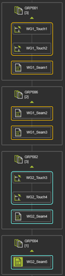 | 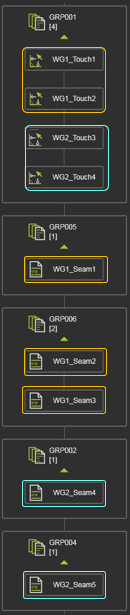 | |
| Unsorted | Sorted |