Controller properties
![]()
Dashboard
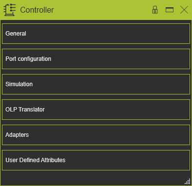
The Controller command opens the controller dashboard. In this dashboard the properties and attributes of the controller can be verified and modified when needed. The dashboard has five containers that can be opened or closed by clicking inside the tab’s frame.
General
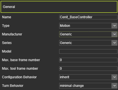
This container opens the general information of the controller.
The controller has the following general attributes. At creation of the controller the default values for the attributes are given by the software, depending on the choice of type of controller.The attributes are shown and editable in the dashboard function of the Controller Builder Workbench.
| Attribute | Description | Remark |
|---|---|---|
| Name | The name of the controller | A name for the controller is mandatory. |
| Type | The type of the controller according to the classification. | The Type is selected from a predefined drop down list. |
| Manufacturer | The manufacturer name of the controller. | The Manufacturer is selected from a predefined drop down list. |
| Series | The series name of the controller. | The Series is selected from a predefined drop down list. |
| Model | The model name of the controller. | The attribute can be left empty. |
| Max Base Frame Profiles | An index value of the number of base frames that can be managed by the controller. | |
| Max Tool Frame Profiles | An index value of the number of tool frames that can be managed by the controller. | |
| Configuration Behavior | The default configuration behavior of the controlled resource(s). | The predefined list includes the options |
| Turn Behavior | The default turn behavior of the controlled resource(s). | The predefined list includes the options |
Port configuration
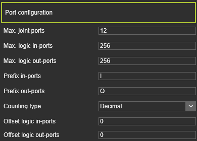
This container opens the signal port configuration information of the controller.
A controller has the following port configuration.
| Attribute | Description | Remark |
|---|---|---|
| Max. joint ports | The maximum number of joints and other axes the controller can connect to. | |
| Max. logic in-ports | The maximum number of logical ports at the input side of the controller. | |
| Max. logic out-ports | The maximum number of logical ports at the output side of the controller. | |
| Prefix in-ports | A prefix string for the input port names. | A vendor specific prefix is automatically inserted here, but can be edited. |
| Prefix out-ports | A prefix string for the output port names. | A vendor specific prefix is automatically inserted here, but can be edited. |
| Counting type | The number- and counting type of the ports. | The counting type is usually vendor specific. It can be |
| Offset logic in-ports | The offset value at counting start of the input ports. | The offset value must be of the same system as the counting type. Example: Starting with a byte address I10 means an offset value of 80. |
| Offset logic out-ports | The offset value at counting start of the output ports. | The offset value must be of the same system as the counting type. Example: Starting with a hexadecimal address QA means an offset value of 10. |
Simulation
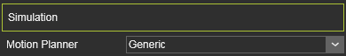
This container opens the simulation definition of the controller.
To run a proper and reliable simulation the controller needs to have defined the correct simulation engines for the resources it will manage.
| Attribute | Description | Remark |
|---|---|---|
| Motion planner | Drop down list of available motion planner strategies. Robot and machine manufacturers usually build in their own motion planning strategy. | The predefined list includes the strategies 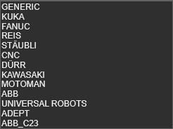 The Generic strategy is a general FASTSUITE Edition 2 strategy for common use. The Generic strategy is a general FASTSUITE Edition 2 strategy for common use. |
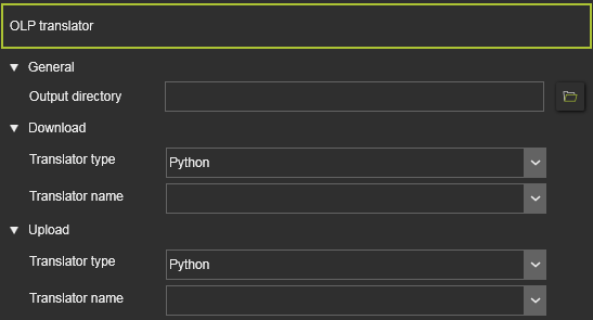
OLP translator
This container opens the editor to set the properties of the programming output.
To be able to export the simulated program to the physical robot or manufacturing machine, the program needs to be written in the correct, corresponding language.
| Attribute | Description |
|---|---|
| General | |
| Output directory | The path and file name where to store the program output file. |
| Download / Upload | |
| Translator type | The data format of the translator, to filter the list of available translators. It can be selected between: |
| Translator name | From the drop down list, the required downloader or uploader file, with the translator definitions and commands, has to be selected. A translator is vendor specific. Depending on the controller manufacturer, the system searches in the plugin folder(s) for the available translators of that manufacturer. |
Adapters
This container opens the adapter information of the controller. The editor shows the individual adapters and their definition.Selecting an adapter will cross highlight it in the 3D View and its name
The adapter has the following base attributes. At creation of the adapter the default values for the attributes are given by the software, depending on the choice of type of adapter.The attributes are shown and editable in one of the dashboard functions of the different Workbenches that support the creation of adapters.
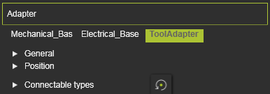
The Adapter container opens with a vertical list with all the defined attributes within the component, shown by their names. Selecting one of them will show its attributes sorted in two groups. A cross highlighting in the 3D View and the dashboard UI appears.
| Attribute | Description | Remark |
|---|---|---|
| Name | The name of the adapter. | A blank name is allowed. |
| Type | The type of the adapter according to the classification. 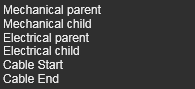 | |
| Capacity | Defines how many adapters can be connected to this one. | Applies only to socket type adapters. |
| X, Y, Z | The X,Y and Z coordinates of the adapter. | Coordinates are set to the component’s global coordinate system. |
| Roll(X), Pitch(Y), Yaw(Z) | The roll, pitch and yaw orientation of the adapter. | Orientation angles are set to the component’s global coordinate system. |
| Defines which classes of components can plug in to this adapter. Selection through the corresponding class icon. | Applies only to mechanical socket adapters. The Reset command switches the definition back to the base setup | |
The resource classes. 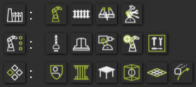 | Picking the category icon sets all components of the category. | |
| The classes humans, controller and workpiece. |
User defined attributes
This container opens the user defined attributes of the controller. The editor shows the attributes and their definition. User defined attributes can be added, modified and deleted here.
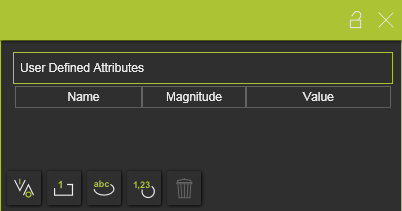
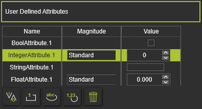
There are four main types of use defined attributes.
| Type | Description | Remark | |
|---|---|---|---|
| Boolean | An attribute that has either the value True or False. | The value is set True by pressing the value button | |
| Integer | An integer number of different magnitudes. For each magnitude the unit is set and displayed automatically. | A drop down list is available to specify the required magnitude 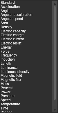 | |
| String | A text based attribute. | ||
| Float | A real number of different magnitudes. For each magnitude the unit is set and displayed automatically. | A drop down list, same as for the integer attribute, is available to specify the specific magnitude. |
The user defined attribute can be added by clicking on the attribute type button. The attribute will be added to the list and is given a default name and value. Selecting the name or value enables to modify it.
The currently active, selected, user defined attribute can be removed by pressing the
Deletecommand button
![]()
.