Manipulator position dashboard
![]()
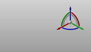
When the center sphere of the Manipulator is selected, the position dashboard appears. This dashboard shows the position coordinates and orientation angles of the Manipulator. The position of the Manipulator is specified by X-, Y- and Z-values. The orientation is specified by the angles Roll rotation around the X-axis, Pitch rotation around the Y-axis and Yaw rotation around the Z-axis.
The dashboard is not only for information, the displayed values are editable parameters. Changing a position or rotation value will interactively adjust the Manipulator.
Position and rotation values can be entered directly by typing the value. The spinners in the value field can be used to raise or lower the value in steps.
Clicking the right mouse button when over the spinners will open a small step size window.
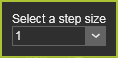
Here the step size can be set. From the drop down list of predefined step sizes the preferred size can be chosen. But is also gives the option to set a user defined size. The defiend step size is stored in the user settings and is therefore kept for any next session.
There is a step size for the position spinners and one for the rotation spinners.
There are three modes in which the position and orientation of the Manipulator can be defined.
 | ||
| Displays and edits the position and rotation relative to the global coordinate system of the 3D View. | 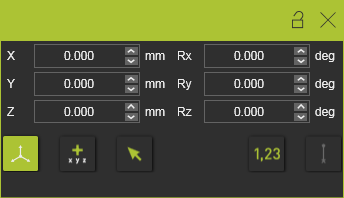 | |
| Displays and edits the position and rotation relative to the last position of the Manipulator. Setting the mode, or resetting the mode, will switch all values to zero (0), from where a new relative (increment) value can be defined. | 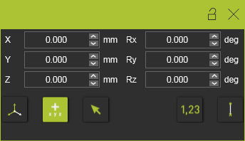 | |
| Displays and edits the position and rotation relative to a local reference coordinate system. The local reference coordinate system has to be selected after the mode has been activated or re-started. The position window will be switched off temporarily until the reference coordinate system has been selected. | 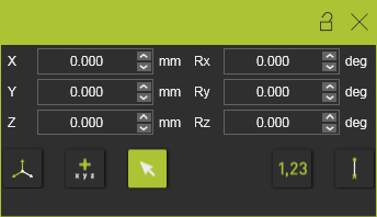 | |
| Values for the position and orientation are automatically rounded to the nearest value according the step size of the parameter. This applies to both dragging the Manipulator as well as inserting a value here. This action will be ignored when the Manipulator is dragged or snapped directly on any reference element, like a frame or geometrical object. | 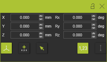 | |
| Shows or hides a black connection line between the reference and the new position, when applying one of the two relative position commands. | 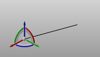 |
The last applied mode remains active each time when calling out the Manipulator.