Multi point calibration
Multiple point calibration
![]()
Calibration
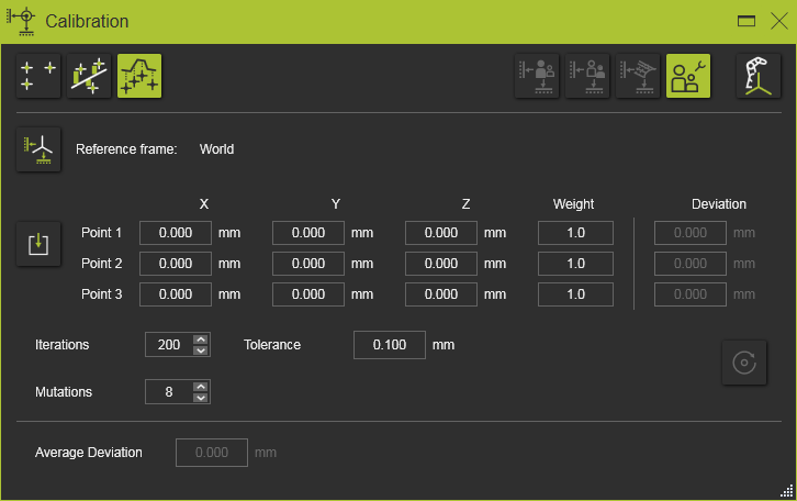
Multi point calibration is used to closely as possible position a workpiece in the virtual workcell, based upon measured points on the surface of the real workpiece in its built-in position. The method computes the axis transformation from the measured points cloud to the digital workpiece.
Reference frame
![]()
The Reference frame button is an option to specify the reference coordinate system (calibration reference frame) in which the measured points are being imported. By default the World coordinate system is used.
Import
![]()
The input for the calibration is a set of measured coordinates. These coordinates usually are imported from an external file, but manual entering or modifying these values is possible.
The input file with the measured points is a simple text file that is read line by line. It has an optional first line with the unit indicator, followed by three lines of coordinates. Coordinate lines have to contain exactly three coordinate values, separated by semicolon. Each line is interpreted as the X, Y and Z coordinates of a single point. By default these points are imported in the 3D space world coordinate system, but another reference coordinate system can be defined in the dashboard. An example of such import file is shown below.
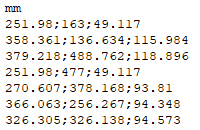
The unit of the coordinates is specified in the first line of the file. Any unit, known by the software can be applied here. It can be written in full name or as the standard abbreviation of that unit. When however the unit line is missing in the file, the import will read the coordinates with the system default unit.
The decimal sign of the coordinate is language and region settings independent. It always has to be a point ”.”.
Although the unit in the import file has been specified, the dashboard will display the coordinates according the current system units. The values then are converted when needed.
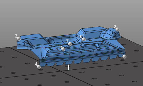
With the Import button the measured data of the object’s position in the real workcell is read. A file browser appears to select the data file. The measured coordinates are displayed as white spheres in the 3D space. This default color can be changed in the Settings.
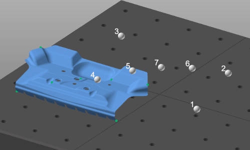
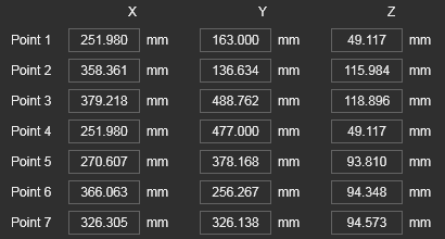
The result of the import is displayed in the dashboard. The coordinate values of the measured positions can be modified here when necessary.
The calibration method includes the following parameters to control the computation.
| Weight | The weight factor determines the impact of the measured position on the overall calibration. It can be interpreted as an internal multiplication of the number of measured points at the same position. The more points you have, the higher the impact during the computation. |
| Iterations | The maximum number of iteration steps to compute the workpiece position from its position into the measured cloud of points. |
| Tolerance | The value to terminate the computation. When the average deviation of a computation step is lower than the tolerance value, the computation is terminated automatically. |
| Mutations | The maximum of variations of the workpiece rotation to match the measured cloud of points A mutation is the variation of the workpiece’s original position, from which the iterative computation will start. A mutation will be reached while rotating the workpiece over its X- or Z-axis. The maximum number of mutations covers the whole hemisphere while rotating in equal steps up to 2pi over the X-axis and 1pi over the Z-axis. For example; with max. of 8 mutations, the workpiece will be rotated over its X-axis in steps of 90 degrees and over its Z-axis in steps of 180 degrees. |
Execute
![]()
The calibration will be computed when pressing the Execute button. In contradiction to the other calibration methods, this one needs to be executed manually.
The dashboard stays open. It allows to change anything at the input and to recompute the calibration. Closing the dashboard or starting any other command terminates the process with the last computed solution.
After the result has been computed the deviation between the workpiece’s new position and the measured cloud of points is displayed in the command panel.
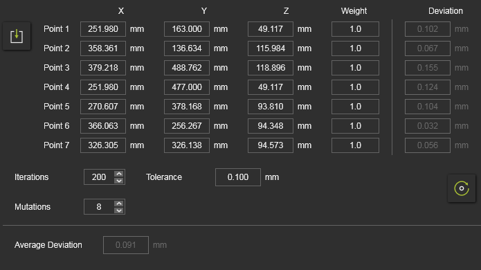
For each individual measured position the deviation is being displayed, as well as the average of all deviations.
The calibration has three levels of interpreting the result, that is shown in the calibration panel, by coloring the average deviation value and as indicator in the 3D view after each execution run:
 | The calibration is validated as successful when the average deviation and the deviation of the individual points is smaller than or equal to the defined tolerance. |
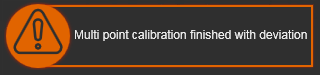 | The calibration is validated as warning when the average deviation is smaller than or equal to the defined tolerance, but the deviation of the individual points may be larger than the tolerance. |
 | The calibration is validated as failure when the average deviation is larger than the defined tolerance. |
Calibration result option
The result of the calibration is a transformation of the component. The way it will be applied can be defined in the result options.
| Initial situation. |  | ||
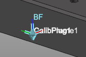
| Create a new child adapter | In the root of the calibrated component a new mechanical child adapter will be created; CalibPlug. The component itself is not transformed. The new adapter can be used to reposition the component according the calibration coordinates. | 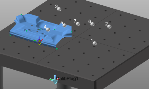 | |
| For the following result options, the component has to be attached to another one; for example the workpiece positioner mounted on the floor. The child adapter of the to be calibrated component has been connected to the parent adapter of the other component. | |||
| Define the transformation | The component will be moved into the calibrated position, but the adapters are not changed. There will be an offset between the two connected components. A connection line between the two adapters is displayed. | 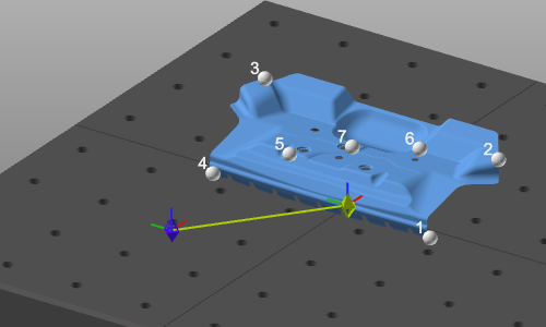 | |
| Move the child adapter | The component is moved to the calibrated position. Its child adapter is moved along with the transformation. This generates a modification of the component definition. It therefore needs to be saved again. | 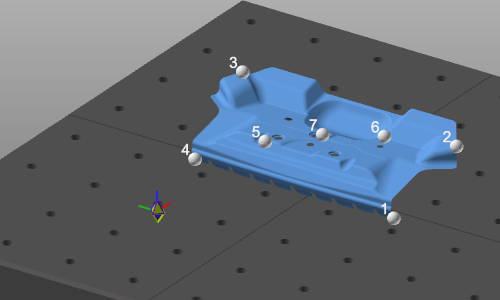 | |
| Move the parent adapter | The component is moved to the calibrated position. The parent adapter of the connected component is moved along with the transformation. This generates a modification of that connected component definition. It therefore needs to be saved again. |  |
![]()
The Create base frame option is a switch to create an additional base frame at the calibration adapter.