Interactive simulation
![]()
Joint motion
This is a very convenient function to manipulate a kinematic object with only the mouse. When the mode is activated, the 3D View only shows the resource with its skeleton of joints and connections between them. Joint frames and names are automatically hidden.
Each driven joint, or it attached geometry can be picked with the left mouse button. The joint becomes active and its graphic representation shows a colored symbol representing the limits and local position of movement of that joint. While keep pressing down the left mouse button and dragging the mouse will then move the attached geometry. Although the image below only shows the rotation joint, the mouse interaction also applies for translational joints.
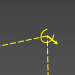 | 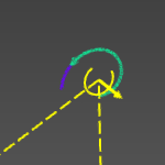 | |
| Default | Interacted |
When interacting a joint that is part of a kinematic chain, all other joints that are connected downstream (children) to the interacted joint will move along with the manipulation. Only, and of course, their relative positions (location and angle) will not change during this manipulation.
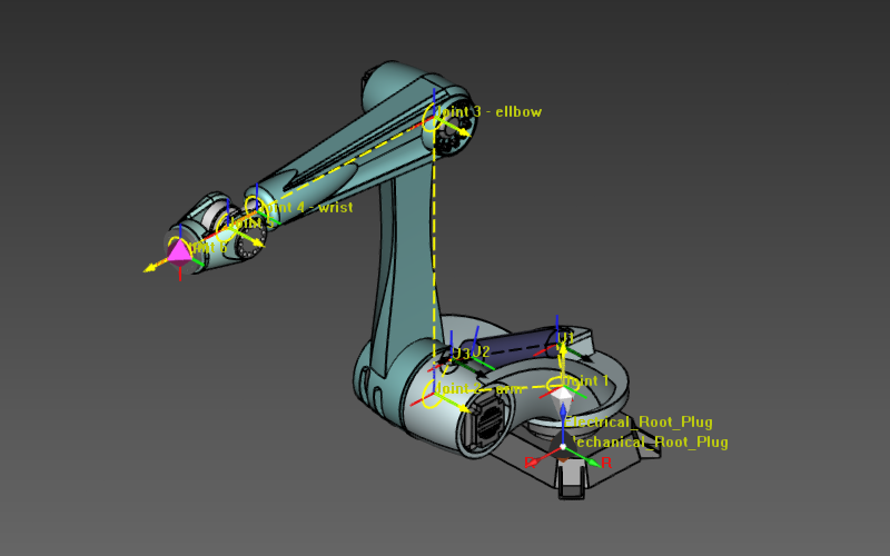 | 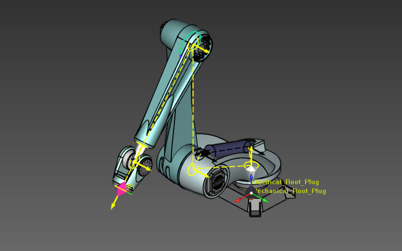 | |
| Before | After |
Inverse kinematic
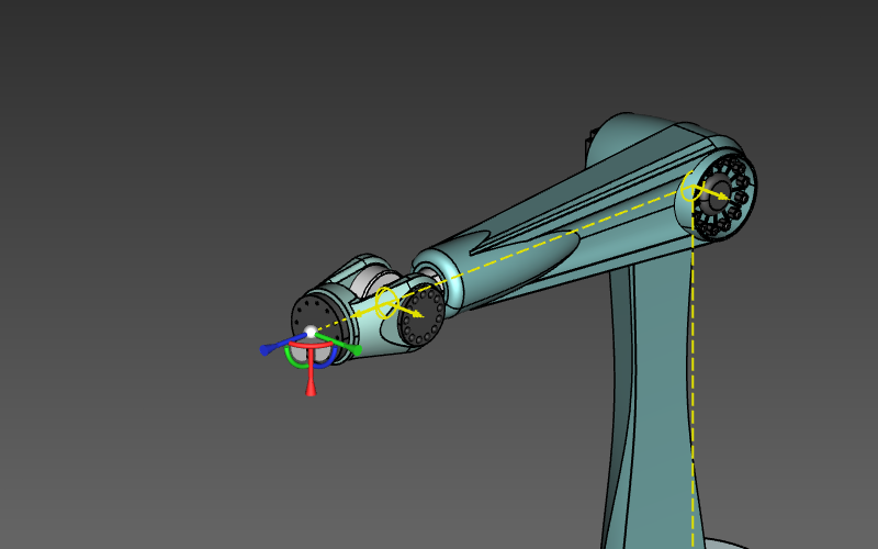
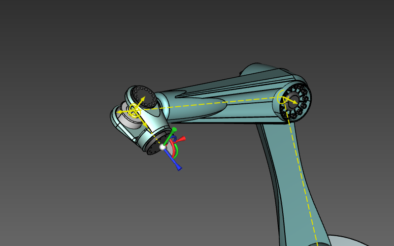
When the resource is provided with a tool frame it will be possible to simulate the resource by using the inverse kinematic computation. The tool frame interactive manipulator will become visible and similar to the 3D Manipulator, it can be dragged (translated and rotated) to a desired position in the 3D View. Now not a single joint is manipulated, but based on the position and angle of the tool frame, all the internal positions and angles of the joints are calculated.
 |  | |
| Before | After |
![]()
It can be possible to drag the tool frame manipulator to a position or angle that lies outside the range of the kinematic chain. In such case the resource itself will stop at its limit position, where the tool frame manipulator can be dragged further. A beam symbol is shown between this limit position and the manipulator’s position to indicate the out of range motion.
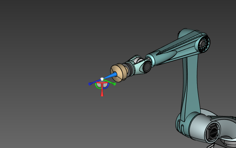 | 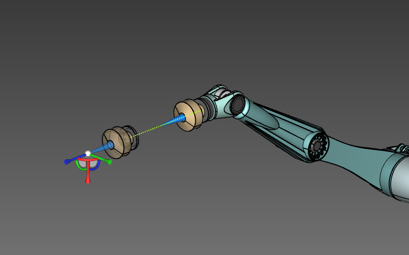 | |
| Inside reach | Outside reach |
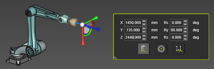
When the center sphere of the Manipulator is selected, the position dashboard appears. This dashboard shows the position coordinates and orientation angles of the Manipulator. The position of the Manipulator is specified by X-, Y- and Z-values. The orientation is specified by the angles Roll rotation around the U-axis, Pitch rotation around the V-axis and Yaw rotation around the W-axis.
The dashboard is not only for information, the displayed values are editable parameters. Changing a position or rotation value will interactively adjust the Manipulator.
Position and rotation values can be entered directly by typing the value. The spinners in the value field can be used to raise or lower the value in steps.
Clicking the right mouse button when over the spinners will open a small step size window.
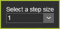
Here the step size can be set. From the drop down list of predefined step sizes the preferred size can be chosen. But is also gives the option to set a user defined size. The defiend step size is stored in the user settings and is therefore kept for any next session.
There is a step size for the position spinners and one for the rotation spinners.
There are three modes in which the position and orientation of the Manipulator can be defined.
| Displays and edits the position and rotation relative to base frame of the OLP setup. | 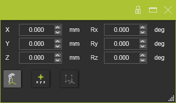 | |
| Displays and edits the position and rotation relative to the current position of the manipulator, from where it is moved. Setting the mode, or resetting the mode, will switch all values to zero (0), from where a new relative (increment) value can be defined. | 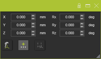 | |
| Displays and edits the position and rotation relative to a toolpath element. The toolpath element has to be selected before the mode can be used. | 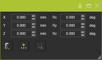 |