Workpiece geometry
![]()
The Geometry command is a helpful command to maintain the geometry of the workpiece.
To make the workpiece useful for manufacturing or process programming and simulation, 3D geometry can be imported and assigned to the workpiece definition. The 3D geometry is imported with the Import command from the Document toolbar. Various CAD sources are supported here.
When the imported geometry will be used for manufacturing or process programming it is mandatory to apply the Exact geometry import (Settings). If not applied, the surface geometry is converted into a triangular mesh with complete loss of geometrical and topological information and becomes only usable for rendering and simulation visualization.
After import, the geometry is visible, but has not become part of the workpiece yet. Saving the workpiece at this stage and closing the document will loose the geometry.
To have the workpiece represented with the imported geometry, the geometry has to be attached to the workpiece definition. In any workbench or function within the software, the imported geometry is displayed normally, with its original or manipulated colors. When this command is active the display shows which geometry is or is not already attached to the component. Attached geometry is given a new temporary color, differently per frame or joint. Non-attached geometry is displayed in a light gray shaded mode of the original color.
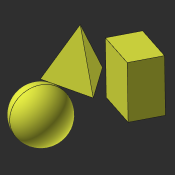 | 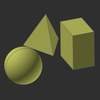 | 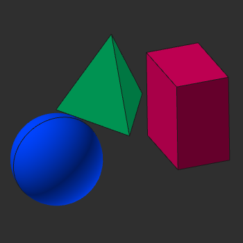 | ||
| Normal display | Geometry display non-attached | Geometry display attached |
The geometrical objects, called bodies, can be selected and attached. A Pie menu has to be called to do such.