Teach toolpath
![]()
Teach toolpath
Teach is a collection of different activities and operations to modify the toolpath that has been computed initially. This can be changing the path itself in context of 3D position, as well as changing the position and motion of the manufacturing equipment to guide the tool along the path.
Teaching is done interactively in the 3D View, with using the Teach panel dashboard or the Toolpath monitor dashboard.
Interactive teach
With the interactive teach in the 3D View a toolpath element, or a range of elements, is manipulated. Its position or orientation can be changed by manual interference of the user or by the system interpolation algorithms.
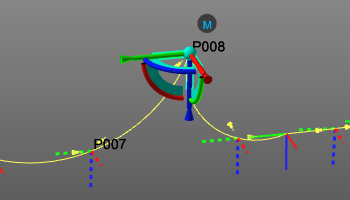
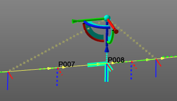
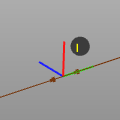
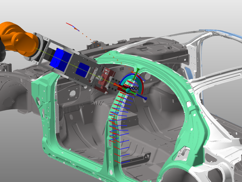
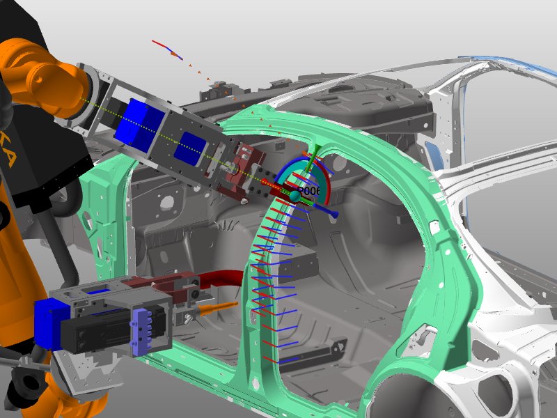
Picking a tool path element will place the tool center point (TCP) with a teach manipulator and its attached resources, at that picked position. If the selected position is not reachable for the resource, the manipulator will still be located there, including a transparent copy of the tool to indicate that state.
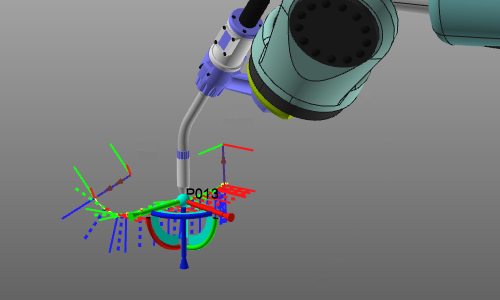 | 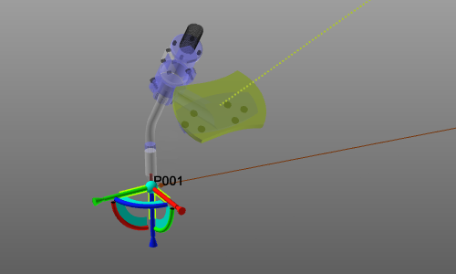 | |
| TPE reachable | TPE not reachable |
The toolpath element now can be repositioned by moving the manipulator or by calling its Position dashboard. In both cases the toolpath element moves along with the manipulator. However, the UI response has two possibilities. In the General settings and corresponding in the Teach dashboard, there is an option how the system should response.
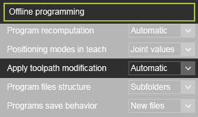 |  |
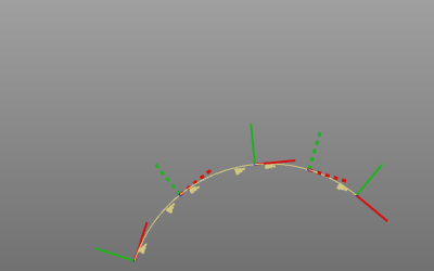
In the Automatic program recomputation mode, the toolpath is updated immediately to the change of the position(s). In the Manual program recomputation mode, the new manipulator position shows three connection lines to the existing toolpath. Here the user has an option at each line to confirm the system to update the toolpath.
 |  | |
| Automatic update | Manual confirmation |
The blue tool path line indicates a reposition of the current tool path element. The brown lines indicate the tool path change in case a new tool path element is going to be placed at the manipulator’s position and if this new element has to be placed before or after the current element.
Any taught action automatically creates an event of that action. Deleting that event will reset the tool path element to its original state.
Teaching supports to select multiple toolpath elements, including via points, to have a certain operation being executed on those elements simultaneously. Although when using a trap window for the multiple selection, the via points are not included automatically. They need to be picked manually while using the Ctrl-key pressed.
The teach manipulator will be placed on the first element of the selection.
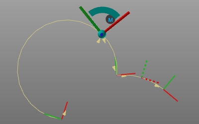
The pie menu on the manipulator or on the connection lines in case of manual update mode, has several additional commands to modify the toolpath. Additional toolpath elements can be added to fine tune the path and existing elements can be inverted.
Manually inserted toolpath elements are given a flag Inserted, an event symbol, placed near the element.
The pie menus on the TPE and toolpath contour element, when hovering over it, also include several of these modification commands.Toolpath elements can be suppressed to ignore them when computing the path. They also can be inverted. Inserted elements can be removed. And for smoother motion of the tool, the path, or parts of it, can be optimized with some interpolation algorithms.
Interactive teach on toolpath via points
Circular toolpath motions distinguish from linear or PTP motions by passing an intermediate via point. The via point with the start and end point of a toolpath section determines the circular radius of the path.
Interactive teach on such a via point is supported, but with restrictions. The circular path remains circular after teaching the via point.
 |  | |
| Before teach | After teach via point |
And furthermore, the teach on via points does not support other teach functions like they are available when teaching regular toolpath positions.
Simulation based teaching
When the toolpath position has been picked for teaching, the TCP is going to be placed at that position. The system supports two methods how this can be executed.
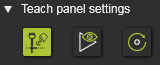
In the General settings and corresponding in the Teach dashboard, the wanted method has to be set.
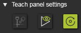
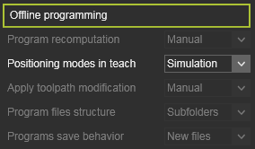 |  |
With the method Joint values (= de-activated in the teach panel), the TCP of the active controller, i.e. robot or machine, will be placed at the selected toolpath position by simply calculating the joint values of its resource for that position and those of possible other connected kinematic devices, such as turn tables.
With the method Simulation (= activated in the teach panel), a program simulation will run in the background. The simulation simultaneously will be scanned for incidents that occur before the wanted position has been reached.
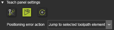
When no incidents occur, the TCP is placed at the picked position. However, an additional action has to be specified how to continue in the event that an incident occurs during simulation before the wanted position has been reached.
| Simulate to the issue | The simulation stops at the (first) incident position and the TCP is placed there to highlight and focus on the problem. |
| Jump to selected toolpath element | The simulation is terminated and the TCP is placed at the selected position by applying the joint values. |
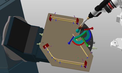
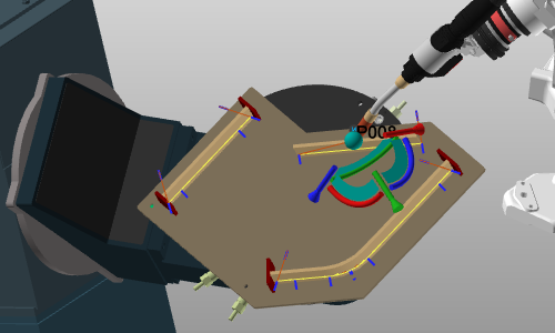
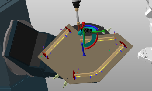
Dynamic teaching of multiple robots or machines
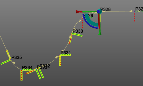
Modifying a toolpath, a position can only be done on the active program of the selected, active controller. In a manufacturing project, several controllers with their connected robots or machines may operate together. Of each controller, the active program is displayed then, like in the example below.
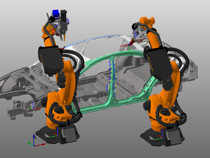
While teaching and picking a toolpath position to modify it, the system will automatically then change to the controller that runs the program of that toolpath and places the related TCP at that position.
 | 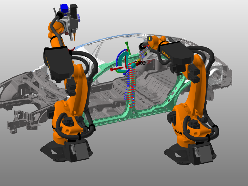 |
With the Teach positioning mode set to Joint values, only the TCP of the robot or machine from the active controller will be placed at the selected toolpath position by applying the calculated joint values to reach that position. Resources (TCPs) of other controllers remain at their initial position.
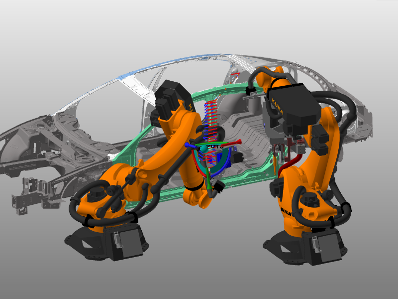
With the Teach positioning mode set to Simulation, all TCPs are placed at their position corresponding in simulation time to the selected toolpath position. With this feature the impact of a teach can be shown with respect to all other programmed robots or machines and possible error situations can be detected easier.
Teaching external axes
Teaching axes of external devices works the same as for driven axes of the robot or machine. But with an additional option: Keep TCP.
With the option it is specified if the tool center point has to stay at its original position while teaching the external axis, or if it has to keep its relative position and thus moves along with the taught external axis.
 |  |  | ||
| Before teach | Teach without Keep TCP | Teach with Keep TCP |
Teach panel
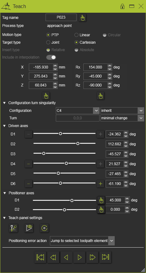
(example)
In the Teach panel the position of the toolpath elements is shown and can be modified. And furthermore the motion between the toolpath elements can be controlled here.
Besides the information of the toolpath and its toolpath elements, this panel also shows the kinematic state of the resources that play a role, including the external, in steering the tool along that path. One section is for resource configuration and singularity management. In the other section the driven internal and external axis of the resource kinematics can be optimized or used to change the toolpath.
Toolpath monitor
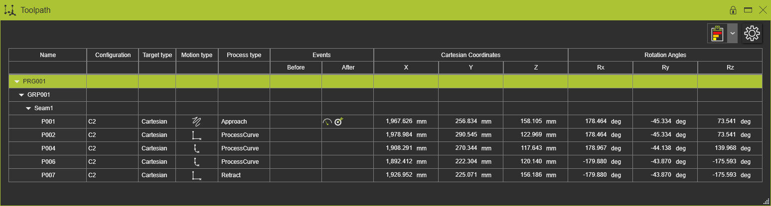
(example)
The toolpath monitor is the other dashboard in which the computed toolpath can be modified or enhanced. A cross highlight between a selected toolpath element in the 3D and / or in the dashboard is visible.
Teaching commands are available when calling the pie menu on a or multiple toolpath positions.