Contour process geometry
Contour process geometry is built from surfaces and their boundaries. The process geometry is defined by a set of control points that lies on the surface. A search engine connects these control points with a curve element. The curve elements have a normal direction definition that has been derived from the reference surface.
Create
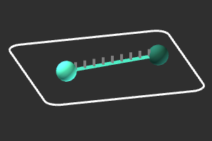
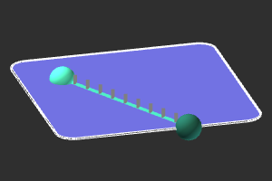
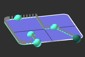
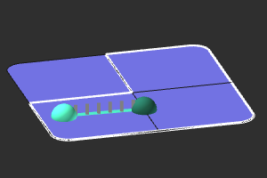
There are at least two control points needed to start the contour search engine.
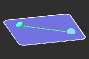
Control pints are displayed as spheres. The blue ones are the start and intermediate points, the green one is the end position of the contour. As soon as two points have been placed on the reference surface the contour between them is searched for and displayed in blue. Vector markers are displayed along the contour element to indicate the normal orientation of the contour, referring to the local normal direction of the reference surface.
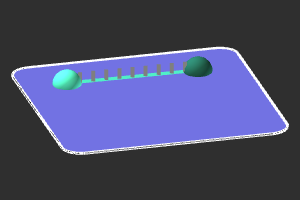
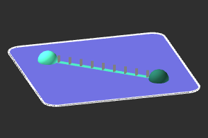
When creating a free form contour or editing an existing contour, the control points are positioned based upon WYSIWYG, i.e. the picked mouse position on screen. New points can be added to the last position by simply picking a new position on the reference surface. It extends the contour with a new element.
 |  |
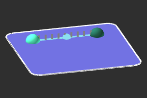
Or hovering over a contour element enables to insert a control point and split the element in two new ones.
|  |  |
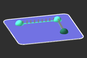
Control points can be moved freely. Picking a point enables to move it anywhere on the reference surface.
|  |  |
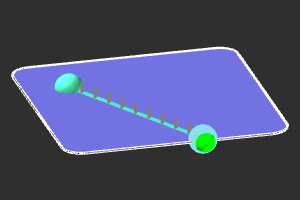
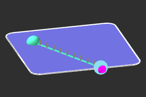
When moving it near to the reference boundary, a green marker appears to drop it exactly onto the boundary. Pressing the ![]() key turns the marker into purple to indicate the exact drop action. Releasing the control point then will drop it spot on the boundary.
key turns the marker into purple to indicate the exact drop action. Releasing the control point then will drop it spot on the boundary.
 |  |  |
On a control point the Pie menu can be opened to have access to other manipulation functionality.

The contour element has a Pie menu for modifying the contour search strategy.

And on the normal markers the Pie menu can be called to manipulate the normal direction.

Contour search engine
A search engine tries to connect two control points with each other to build the contour. Because different solutions would be possible the search engine uses a strategy to find a result. The software supports three strategies.
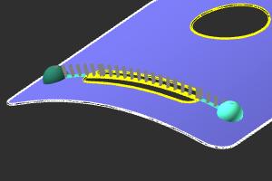
| Searches for the shortest track over the outer boundaries of the reference surfaces. | 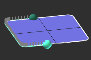 | |
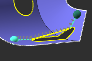
| Searches for the shortest track over the inner edges of the reference surfaces. | 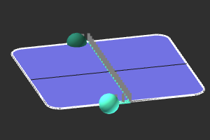 | |
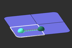
| Searches for the shortest distance track between the control points, over the reference surfaces. | 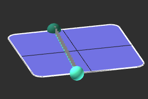 |
The strategies as shown above are listed in the order of priority. Initially the outer boundary search, looking for the shortest track along that boundary, is the default strategy when creating a new process geometry. However, when it cannot be applied or does not lead to any possible result, the second strategy in line is applied. And when that strategy also does not lead to any result, the last strategy is applied, where control points are linear connected, the shortest possible distance between them.
Boundary and inner edges can only be found when at least two control points in line lie exactly on the boundary or inner edge.
Once a solution has been found, for each contour element the strategy can be set individually, like in the example below.
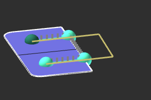
The contour search is an intelligent engine that can cross gaps and holes in the reference surface.
Where possible the gap or hole is closed by making use of the (interpolated) information of the reference surface. Otherwise the gap or hole is closed by a linear connection.
 |  |
Reference surface
Control points are positioned on a reference surface. The point cannot be moved outside the boundaries of that surface.
In case the workpiece surface is built out of multiple surface domains the initial result might not be as expected.
The reference surface area can be modified. On the surface itself the Pie menu has to be called.

Then surfaces can be added or deleted from the reference area. Adding surfaces to the area can only be executed when adjacent surfaces meet some criteria to merge them. These criteria are defined in the Search settings.
When done, the Pie menu has to be called again to exit the reference surface area.

Which then leads to the possibility to modify the contour.
When a control point lies on a part of the reference area that has been removed, the control point loses this reference. It immediately turns into red to indicate this situation
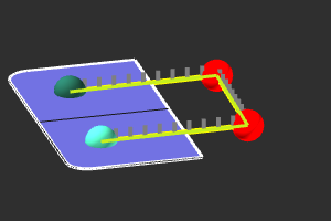
The Pie menu on this unlinked control point has functionality to solve the problem. The control point will be moved to the nearest boundary of the current reference area.
More contour reference information