Resource actors properties
![]()
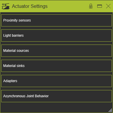
Dashboard
The Actuators dashboard gives an overview of the available actuators in the resource for the simulation and offline programming, as shown in the examples below.
Proximity sensors
This container shows the available proximity sensors located on the resource.
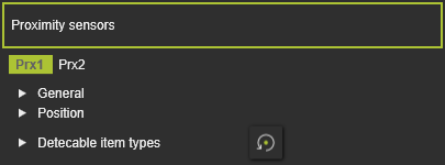
For each sensor the following attributes are defined and can be modified here.
| Attribute | Description | Remark |
|---|---|---|
| Name | The name of the proximity sensor. | A blank name is allowed. |
| Port type | The port type of the sensor, i.e. the switch behavior at detection. | The sensor supports two types: |
| Switching diameter | The diameter of the sensor detection area. | |
| Switching distance | The height of the sensor detection area. | |
| X, Y, Z | The X,Y and Z coordinates of the sensor. | Coordinates are set to the component’s global coordinate system. |
| Roll(X), Pitch(Y), Yaw(Z) | The roll, pitch and yaw orientation of the sensor. | Orientation angles are set to the component’s global coordinate system. |
| Defines which classes of components the sensor can detect. Selection through the corresponding class icon. | The Reset command switches the definition back to the base setup. | |
| The class workpieces. | ||
The resource classes. 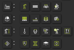 | Picking the category icon sets all components of the category. | |
| The class humans. |
Light barriers
This container shows the available proximity sensors located on the resource.
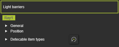
For each sensor the following attributes are defined and can be modified here.
| Attribute | Description | Remark |
|---|---|---|
| Name | The name of the proximity sensor. | A blank name is allowed. |
| Port type | The port type of the sensor, i.e. the switch behavior at detection. | The sensor supports two types: |
| Switching diameter | The diameter of the sensor detection area. | |
| Switching distance | The height of the sensor detection area. | |
| X, Y, Z | The X,Y and Z coordinates of the sensor. | Coordinates are set to the component’s global coordinate system. |
| Roll(X), Pitch(Y), Yaw(Z) | The roll, pitch and yaw orientation of the sensor. | Orientation angles are set to the component’s global coordinate system. |
| Defines which classes of components the sensor can detect. Selection through the corresponding class icon. | The Reset command switches the definition back to the base setup. | |
| The class workpieces. | ||
| The resource classes. | Picking the category icon sets all components of the category. | |
| The class humans. |
Material sources
This container shows the available sources for the material flow simulation.
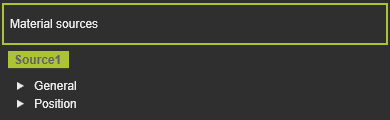
For each source the following attributes are defined and can be modified here.
| Attribute | Description | Remark |
|---|---|---|
| Name | The name of the material source. | A blank name is allowed. |
| X, Y, Z | The X,Y and Z coordinates of the source. | Coordinates are set to the component’s global coordinate system. |
| Roll(X), Pitch(Y), Yaw(Z) | The roll, pitch and yaw orientation of the source. | Orientation angles are set to the component’s global coordinate system. |
Material sinks
This container shows the available sinks for the material flow simulation.
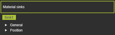
For each sink the following attributes are defined and can be modified here.
| Attribute | Description | Remark |
|---|---|---|
| Name | The name of the material sink. | A blank name is allowed. |
| Width (X), Depth (Y), Height (Z) | The size of the sink activation box. | The box dimensions are defined from the sink’s origin. |
| X, Y, Z | The X,Y and Z coordinates of the sink. | Coordinates are set to the component’s global coordinate system. |
| Roll(X), Pitch(Y), Yaw(Z) | The roll, pitch and yaw orientation of the sink. | Orientation angles are set to the component’s global coordinate system. |
Adapters
This container shows the state of the resource adapters.
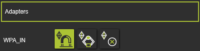
The mechanical socket (parent) adapters are listed here. For each adapter the mechanical connection behavior to a plug adapter can be set by pressing the corresponding symbol.
| Snap | During simulation the plug adapter snaps to the socket adapter, i.e. the component might change its relative position (and orientation) to the parent component to where its has been plugged in. | |
| Grab | During simulation the plug adapter remains its relative position to the socket adapter, i.e. the component remains its relative position (and orientation) to the parent component to which its has been plugged in. | |
| None | During simulation the connection with the plug adapter remains as is and cannot be changed. |
Asynchronous joint behavior
This container shows the resource asynchronous joints and how they are controlled during the simulation.
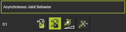
All asynchronous joints of the resource are listed here. For each joint the behavior control can be set by pressing the corresponding symbol.
| Mono stable | The joint moves in the dedicated direction as long as the corresponding input signal does not change. When that signal changes, the joint will move uncontrolled in the opposite direction. The dedicated, active direction of the monostable actor can be inverted with the icon command | |
| Bi stable | The joint moves in positive direction only when the signal of the maximum port is true. It moves in opposite direction only when the signal minimum port is true. The joint does not move when both signals are true or false. | |
| Joint value | The joint moves towards the value that has been set. | |
| None | The joint is not being controlled. |