Program a surface based toolpath
![]()
Command
The Program toolpath command can be executed on surface based process geometry.
When the command has been started, a small window should appear. Here the settings to program the contour are defined.
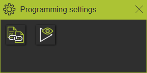
When the panel does not appear, open the pie menu in the 3D space and press the settings command button.
| Setting | Description | Remark | |
|---|---|---|---|
| Operation connection mode | Program connected operations on the same process contour. | ||
| Positioning mode in teach | Dentition of how a tool will be placed at a selected toolpath position. This can be achieved with the robot or machine joint values to reach that position or by simulating the toolpath until the position has been reached. | Applies while teaching an existing toolpath position. |
Compute the toolpath
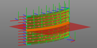
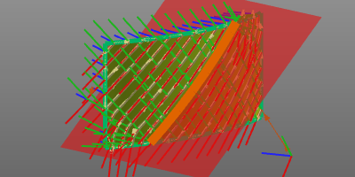
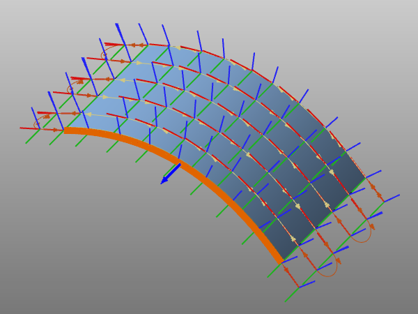
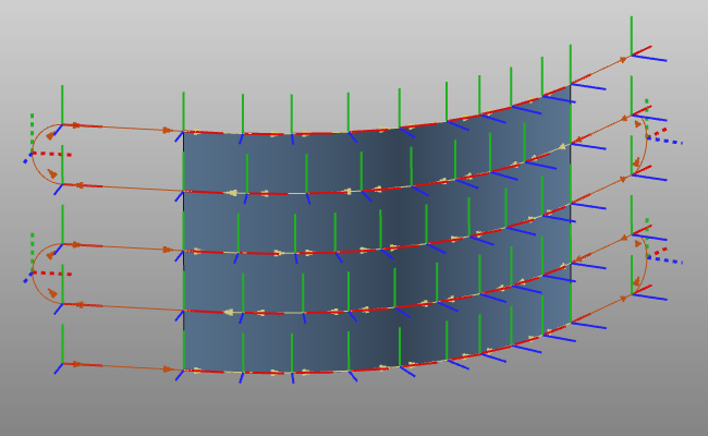
When selecting the surface PG, the manufacturing geometry, i.e. the operation, with its auxiliary information is displayed. There is a slight difference in manufacturing geometry display, depending on the applied strategy to compute the toolpath. This strategy defines the reference guiding curve that is used for the main track direction and orientation of the toolpath.
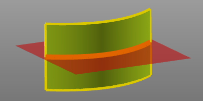 |  | |
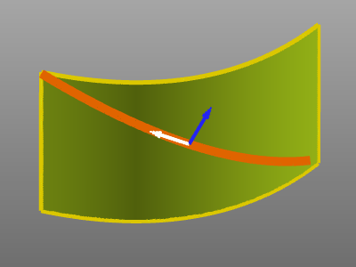
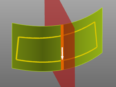
| By intersection plane | By contour |
The red square represents the intersecting plane. This plane intersects the surface to create the orange guide curve. This curve is used as base to compute the toolpath tracks to cover the surface. The yellow contour indicates the outer boundary. The toolpath is computed for the surface area that lies inside that boundary.
To modify the intersection plane for the guiding curve, this red plane can be picked. The Manipulator appears and the position and / or orientation can be changed.
To modify the contour, the pie menu can be opened on the orange guide curve contour itself.

The boundary curve can be used to define a different, i.e. modified area on the process geometry for which the toolpath will be computed.
With the pie menu on the boundary, that boundary can be modified.
Finally, after having optionally defined the boundary and guide curve, the pie menu can be opened on the selected surface(s).
The toolpath will be computed with use of several attributes. In the Programming defaults dashboard these attributes are listed and their values can be set.
After computation, the toolpath is displayed.
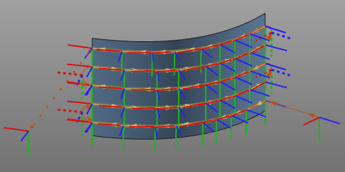
Hovering over the manufacturing geometry, i.e. operation, will show the operation name of the surface.
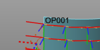
In case the operation and the process geometry are both displayed (Display filters), the operation contour display turns into a dashed mode to enable that both process contour and operation are selectable for any further action.
Multiple selection and sequencing
This applies to both creating a new toolpath and editing an existing toolpath.
To add a new operation after the last selected surface is simply done by picking another process surface with the ![]() keyboard button pressed. The new selection automatically is added after the last step. The sequence is displayed with a sequence number at each individual surface (operation) and adding an operation connection line from the operation up to the next operation in the sequence.
keyboard button pressed. The new selection automatically is added after the last step. The sequence is displayed with a sequence number at each individual surface (operation) and adding an operation connection line from the operation up to the next operation in the sequence.
To add a new operation in between two existing ones, the operation connection line is used. This line can be picked with the left mouse button and dragged on top of the new process geometry. Releasing it onto the new surface will add it and updates the sequence.
Changing the sequence of the operations works similar to adding an operation in between the existing sequence. Pick the connection line of the sequence step that is going to be modified. Then this line is dragged and released onto the operation to connect to and from where the sequence has to proceed.
An operation cannot be removed from the toolpath interactive in the 3D View. To do such, the Active program dashboard is to be used.
Edit the toolpath
Existing toolpaths can be modified here. After selection, the manufacturing geometry and the toolpath is being displayed. Changes made here immediately initiate a recomputation of the toolpath.
On the manufacturing geometry the pie menu can be opened.
The guide curve is colored orange. It has been created from either the intersection plane or from a (user defined) contour.
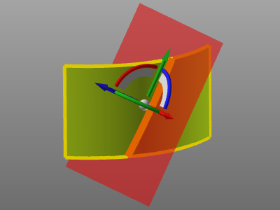
When the guide curve has been created from an intersecting plane, this plane can be modified by picking it. The manipulator appears to change the intersection plane’s position.
 |  |
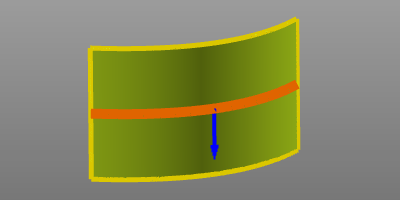
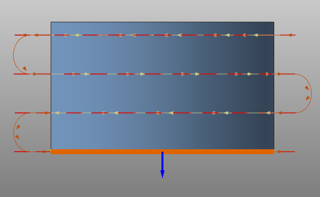
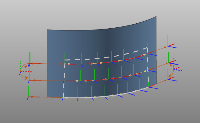
In case the guide curve is a contour, the orange contour is highlighted, including a blue arrow.
The pie menu can be opened on the guide curve to modify it.
The blue arrow at the guiding curve indicates the toolpath direction. A double click on that arrow will invert the direction.
 | 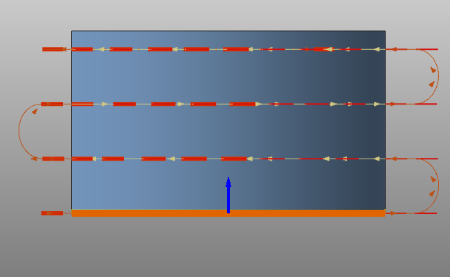 |
And finally the pie menu can be opened on the boundary contour to modify it.
 |  |
Customization script
In general all modifications of the toolpath, the operations (group) or the entire program are done manually. The system does however support the possibility to (partially) automate these modifications.
After the last step in the programming computation a user defined python script can be included to run. With this script not only the last computed toolpath can be modified, but the entire program to which this toolpath belongs. It enables for example to re-organize the different operations, or to include an other naming convention for the operations and toolpath positions.
This dedicated script is named (mandatory) PostProgramProcessGeometries.py and is located in the plugin folder <plugin>\Technologies<technology name>\AuxiliaryCommands\AutoExecute. This can be the default installation plugin or any other configured plugin folder.
The script will only be executed on newly programmed process geometry. Thus, any other change that calls a re-computation of the toolpath or program does not execute the script.