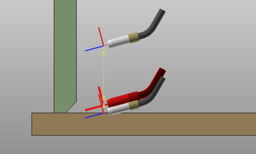
Arc welding touch sensing
![]()
Touch sensing
Touch sensing is a functionality that is not started with a command button. It is a mixture of defining the touch operation conditions and its positions on the welding parts. The operation conditions are to be set in the OLP programming. Setting the touch positions is integrated in the definition and creation of the (welding) contour process geometry.
[link:]
Programming defaults
In the Programming defaults dashboard in the OLP workbench, the tech tab Technology base includes the base selection of the touch sensing definition.
| Touch by point indication Defining the detection points by manually picking on the welding parts. |
The tech tab Touch sensing will display the available attributes to compute the complete touch operation cycle.
[link:]
Touch by point indication
This method currently only works in combination with the Welding contour by projection command to generate the welding process geometry.
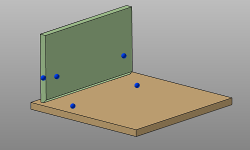
At any time during the process of defining the welding contour, any number of points can be picked on any of the welding parts. Each position is determined by the mouse click on the welding part surface through WYSIWYG. The picked position is marked by a blue sphere, like in the example below.
With the Undo command the last created touch point(s) can be removed again.
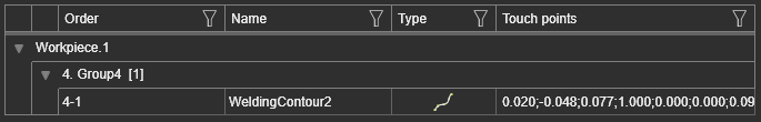
The information of the touch positions is stored with the process geometry that is being created. The positions are being displayed in the Process geometry dashboard.
[link:]
Modifying the touch definition
The positions of the touch detection points currently can only be modified when manually programming the toolpath. At selection of the process geometry, the touch points that have been defined with the process geometry creation, are being displayed in the 3D space. They now can be picked and dragged to any other location on the welding parts.
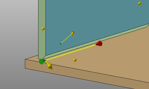
At this stage also new touch positions can be added and existing ones can be removed. Simply pick on the welding part a position to define a new touch point or click an exiting yellow sphere to remove that position. This works on process geometry that includes pre-defined touch positions and on process geometry that does not have any pre-defined touch.
All other touch parameters can be modified once a toolpath has been computed on the process geometry that includes a touch position.
For each detection direction an operation cycle is created. With use of the Active program dashboard in the OLP workbench, the attributes of each touch operation can be modified.
[link:]
More reference information
Automatic:
When creating the (welding) contour process geometry, the system will automatically create a touch position at any welding part that is being used to generate that contour process geometry. Upfront the user only has to define in the programming defaults if he wants to generate these touch positions at the start and / or end of the contour and in what touch direction(s).
There will be no preview of these touch positions, like with the manual indication. However, the positions are being displayed in the Process geometry dashboard.
In the Programming defaults dashboard in the OLP workbench, the tech tab Technology base includes the base selection of the touch sensing definition. Two methods to generate the touch positions are available to choose from.
| Touch by point indication Defining the detection points by manually picking on the welding parts. | |
| Automatic touch Automatic routine to define the required detection points on the welding parts. |
For each way the tech tab Touch sensing will display the available attributes to compute the complete touch operation cycle.