Programming a welding operation
Purpose
In this chapter, the fundamental steps to program a welding operation will be taught.
The basic steps are made to generate the welding path on the different welding contours. The results will be simulated.
Steps
1. Preparation
1.1 Switch to the Offline Programming workbench.
Switch to the OLP workbench
1.2 Open project file
Open the File menu and pick the Open command to load the previously saved project. If the project appears in the list of recently opened documents, then select it there. Otherwise, press the File browser button to open a file explorer and search for the project.
Open a project
![]()
1.3 Select controller unit
The first command that automatically opens in the OLP workbench is the Select controller unit. Here you can select the controller for which the welding programs are going to be created. The selected controller and its connected manufacturing resources are highlighted. Obviously, when the project, i.e. the workcell has only one controller, nothing needs to be done here.
Controller unit
1.4 Unit setup command
Start the Unit setup command and verify that a tool frame and base frame have been pre-selected. The presence of both frames is mandatory to be able to program any operation.
Unit setup
2. Teach a home position
2.1 Apply toolpath modification settings
For the purpose of this course each modification made to a welding path position needs to be confirmed. Verify the Settings for offline programming. Check that the option Apply toolpath modification has been set to Manual.
OLP settings
2.2 Program a first position with the Start teach command on the robot.
Teach a home position
2.3 Modify the inserted position
Change to Events and teach to modify the inserted position. One way is to simply pick a robot axis and drag it. Or use the manipulator to change the position. Confirm the modified position with the Apply changes command.
Modify the welding path position
3. Create the welding process geometry; i.e. the welding contour
3.1 Open Process Geometry Definition Panel
Execute the Generate process geometry command and verify that the process geometry definition dashboard is being displayed. If not, then you can show it by right clicking on the empty 3D space and selecting the Open definition panel command.
Open process geometry definition panel
3.2 Define the fillet weld
Select the definition method Welding contour by projection to define the fillet weld. Pick the first workpiece plate, then drag to the second plate and release there. This method searches the contour by projection of the first plate’s edge onto the second plate.
Fillet weld definition
3.3 Adjust the tool and travel angles
Press the left and right arrow keys on the keyboard to change the tool angle. And press up and down arrow keys to change the travel angle.
Change the tool angle
4. Program the welding path
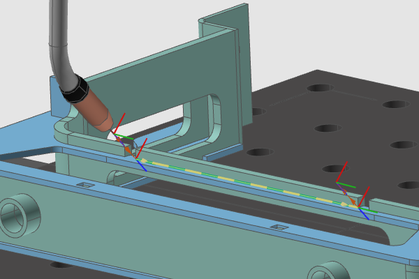
4.1 Automatically generate the welding path
Select the option Automatically generate toolpath and Accept the contour. The welding operation, including all its welding path positions, will be computed.
Compute the welding path
4.2 Simulate the welding program
Press the Play button in the simulation toolbar to run a simulation of the created program.
Simulate the program
4.3 Reset the start state
In the simulation bar click the Reset start state. The start state is generated automatically when the first operation is created.
Start state
5. Navigate along the welding path
5.1 Use Events and Teach to navigate path points
Change to Events and teach. This micro environment allows you to navigate, modify and optimize individual welding path positions. Pick any of the path elements to make the robot jump to it. When two path elements are too close together a selector will appear to pick the desired one.
Navigate along the welding path
5.2 Navigate along the welding path with keyboard
Once a target is selected, use the back and forward keys on the keyboard to navigate to the left or right side along the welding path.
Navigate along the welding path
5.3 Navigate along the welding path with the Teach panel
Open the Teach panel. Click on the middle arrows to navigate along the welding path back and forward. Click the outer arrows to step to the beginning or end of the operation group.
Navigate along the welding path