More cutting operations
Purpose
In this chapter, more cutting operations will be computed. Using the program dashboard you will learn how to modify the execution order of operations and operation groups. The results are simulated to see the effects.
Steps
1. Program cutting operations
1.1 Generate operations for the second and third contour
Switch to Generate process geometry. Notice that for circular holes the system automatically converts the found contour to a circle shape. Run a simulation to see the result.
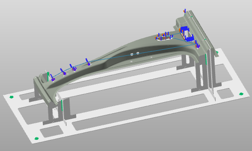
Program a cutting operation
1.2 Open the Active program dashboard
The dashboard can be resized and undocked to best fit your screen.
Active program dashboard
1.3 Reorder operations within a group
Expand an operation group to see the included operations. Hover over operations to see cross-highlighting in 3D. Drag an operation above or below another to change execution order. Run a simulation to see the effect.
Operation sequence
2. New operation group
2.1 Generate operations for four holes on the left side
Program a cutting operation
2.2 Move operations into a new group
Open the Active program dashboard. Select the four created operations and drag them out of the operation group, dropping them below it — a new group is created automatically. If you missed one, drag it into the new group at the desired position.
Creating or merging/unmerging operation groups is useful to modify attributes for all operations in a group in a single action.
Active program dashboard
3. Copy an operation
3.1 Rename an operation group
Select the operation group and click its name to enter edit mode. Change the name and confirm with Enter or by clicking outside the name field.
Rename the operation group
3.2 Duplicate an operation group
Select the operation group. While holding Ctrl, drag the group and drop it at the last position in the program. Rename the group and run a simulation. Duplicating single operations works the same way.
Copy an operation group
3.3 Add and arrange remaining operations
Add the operations for the remaining holes and rearrange them.
Program a cutting operation
4. Program on existing contours
4.1 Build a cutting contour without immediate toolpath computation
In the Process geometry definition panel, disable Automatically generate the toolpath. Create a new cutting contour on the outer side of the workpiece. Accept twice to generate the cutting contour.
Build the cutting contour
4.2 Program the toolpath on the existing contour
Switch to Program toolpath. Select the generated contour. Move the green cone to set the path start. The yellow cone indicates the approach side. Open the pie menu and execute Program this geometry to compute the cutting operation.
Program a cutting operation
4.3 Run a partial simulation
In the Active program dashboard, right-click the operation group and select Play partial simulation.
Partial simulation