Set up the spot welding project
Purpose
Set up the spot welding project by building the shopfloor environment with the welding robot and required equipment, then load the workpiece to complete the setup.
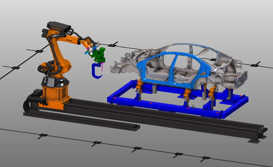
The layout is built from standard equipment such as robot, rail, carrier, and controller. Components are positioned and connected to create the workcell and prepare it for programming.
Steps
1. Preparation (if needed)
Depending on the license package in use, you may work in Layout Builder or Offline Programming for this setup sequence.
1.1 Switch to the Layout Builder workbench
Switch to LB workbench

1.2 Switch to the Offline Programming workbench
Switch to OLP workbench

1.3 Create a new empty document
Create a new empty document before building the workcell. If another document is open, choose whether to save it, close it without saving, or cancel.
Create a new document
2. Build the workcell
2.1 Switch to Drag & snap operation mode
When changing workbenches, Operation mode defaults to Normal. In Offline Programming, switch to Drag & snap to move components in the fixture assembly.
2.2 Add shopfloor components to the layout
Open the project structure and add the floor plan, robot, rail, carrier, and controller from the training data.
Add to layout
2.3 Add the welding gun to the layout
Add the previously built welding gun resource to the layout.
Add welding gun
2.4 Place and connect components
Place components in position with drag and drop while connecting required adapters.
Place components
2.5 Build the electrical connection
Create the electrical connection between the controller and the robot.
Build electrical connection
2.6 Save the layout (if supported)
If you are in Offline Programming, you cannot save a layout directly. Continue to the shopfloor project setup and add the previously saved layout and workpiece there. If layout saving is available in your current workbench/license, save the layout now.
If layout saving is not available in OLP, continue with the next section and add the saved layout and workpiece in the new project.
2.7 Save the layout
The layout document contains shopfloor resources and controllers.
Save layout
3. Build the shopfloor project
3.1 Open a new project document
Open new project
3.2 Add layout and workpiece to the project
Add the previously saved layout and the workpiece, then place the workpiece onto the carrier.
Build project setup
3.3 Verify the file structure
Check the layout tree and file structure. Items marked in red usually indicate unsaved data.
Verify layout structure
4. Prepare for collision analysis
Prepare the workcell for collision analysis during simulation.
4.1 Switch to the Offline Programming workbench
Switch to OLP workbench
4.2 Define collision groups
Define collision groups
4.3 Define collision analysis mapping
Define which collision groups are analyzed against each other.
Define collision analysis
5. Save the project
5.1 Save the setup as a project
Save the setup as a .cenprj project file under an appropriate name.
Save project
Next Step
-> Generate the spot welding program