Build the workpiece
Purpose
Use the Workpiece Builder workbench to build the workpiece surface for the cleaning operation and prepare it for offline programming and simulation.
The workpiece document is created from imported geometry. Dedicated setup information, process geometry, and simulation data are then added before saving the workpiece for later project steps.
Steps
1. Preparation
1.1 Create a new empty document (if needed)
If another document is already open in the running session, create a new empty document. If no document is open, you can skip this step.
Create a new document
Open the File menu and select New. If prompted, choose whether to save the currently open document, close it without saving, or cancel.
2. Define the workpiece
2.1 Verify geometry import settings
To use the workpiece properly in offline programming, import the geometry as exact geometry.
Verify import settings
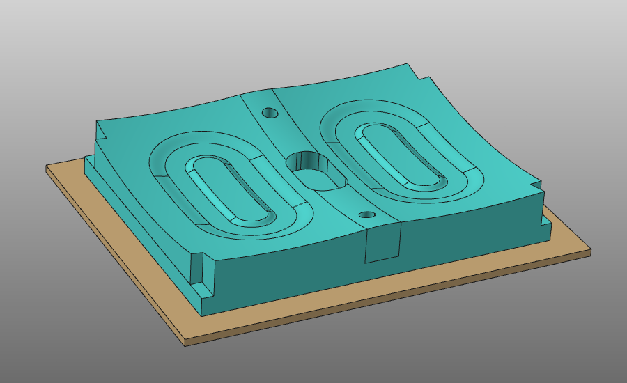
2.2 Import geometry from Mold_Workpiece.stp
Import the geometry from the Mold_Workpiece.stp file in the training data.
Import geometry
2.3 Create a workpiece for the imported geometry
Create a workpiece
3. Build the workpiece shape
3.1 Attach the part geometry to the workpiece
Attach geometry
4. Define the process geometry
Create process geometry for the cleaning operation.
4.1 Set display options for geometry handling
Define settings that make geometry selection easier.
Set display options
4.2 Set process geometry mode to Face
Set process geometry mode
4.3 Select faces to include
Use trap selection to include faces for process geometry. Drag direction determines whether selection is strict (inside only) or touch-based.
Select faces (add)
4.4 Remove unwanted faces
Press Ctrl and use trap selection to remove faces from the set.
Select faces (remove)
4.5 Create process geometry
Create process geometry on the selected surface.
Create process geometry
4.6 Verify process geometry orientation
Check and adjust surface process geometry orientation where required.
Edit process geometry
4.7 Restore global display settings (optional)
Restore display settings
5. Define the simulation object
The simulation object is used to calculate process impact on the surface, for example spray contact time.
5.1 Create a process simulation object
Create a process simulation object for the complete workpiece.
Create simulation object
5.2 Adjust simulation mesh parameters
Modify mesh parameters of the simulation object, such as global triangle size.
Edit simulation object
6. Save the workpiece
6.1 Name and save the workpiece
Give the workpiece an appropriate name and store it on disk.
Save the workpiece
Next Step
-> Build the water jet cleaner