Relief the carrying shape of the support plate
Purpose
The support plate shape that carries the workpiece is computed directly from the workpiece shape. Workpiece tolerances and planned manufacturing processes often require local clearance, so support plates are not in direct contact with the workpiece in all areas.
This page explains how to create reliefs to achieve the required clearance between the workpiece and support plate.
Load the project Fixture_Training_Relief.cendoc from this tutorial library.
Steps
1. Relief at process geometry contour
1.1 Display process geometry
Open Display filters and press Show the process geometry to display the assigned process geometry contours on the workpiece. In this example, they represent laser-cutting process geometry. Then switch off the display again and close the panel.
Display filters
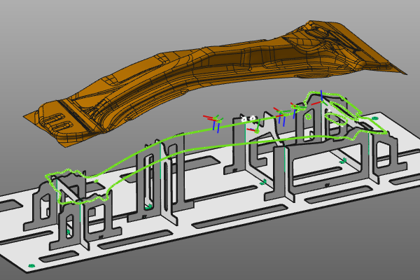
1.2 Check contact areas in perspective view
Inspect the support plates and verify where they fully contact the workpiece, including areas on the manufacturing contour. If needed, open Global settings and set Camera projection to Perspective to inspect the fixture interior more clearly.
Perspective camera projection
1.3 Enable process geometry relief
Open the Fixture parameter dashboard. Set Manual update to Automatic so changes are applied immediately. Then open the Relief container and activate Process geometry relief. Review the updated support plate shape.
Relief on process geometry
1.4 Adjust circular notch radius
![]()
The relief shape is controlled by several parameters. Change Circular notch radius and observe how it affects the relief geometry.
Relief parameter adjustment
2. Corner relief
2.1 Detect corner relief candidates
![]()
Activate Corner relief detection. Each support plate is checked against the search parameters to find corners that can be relieved. Detected corners are marked with a green relief symbol.
Corner relief detection
2.2 Create detected corner reliefs automatically
Enable Create detected relief. Detected corner reliefs are computed automatically with default parameters wherever possible.
Auto-create corner relief
2.3 Create or edit corner relief manually
Corner reliefs can also be created or edited manually. Use the green symbol and run Create/Edit corner relief. In the parameter panel, set the required values and press Accept to create or update the relief.
Important: Corner reliefs can only exist while detection is active. If detection is switched off, they are deleted automatically. Also, if a support plate change triggers a full recomputation, the corner relief is reset to its initial shape and size.
Create/Edit corner relief