Map the port signals
Purpose
Use the Layout Builder workbench to define signal communication between the controller and resources.
Electrical connections between resources and the controller are used to automatically assign signals to the controller ports.
Steps
1. Preparation
1.1 Switch to the Layout Builder workbench
Switch to Layout Builder
![]()
2. Map the signal ports
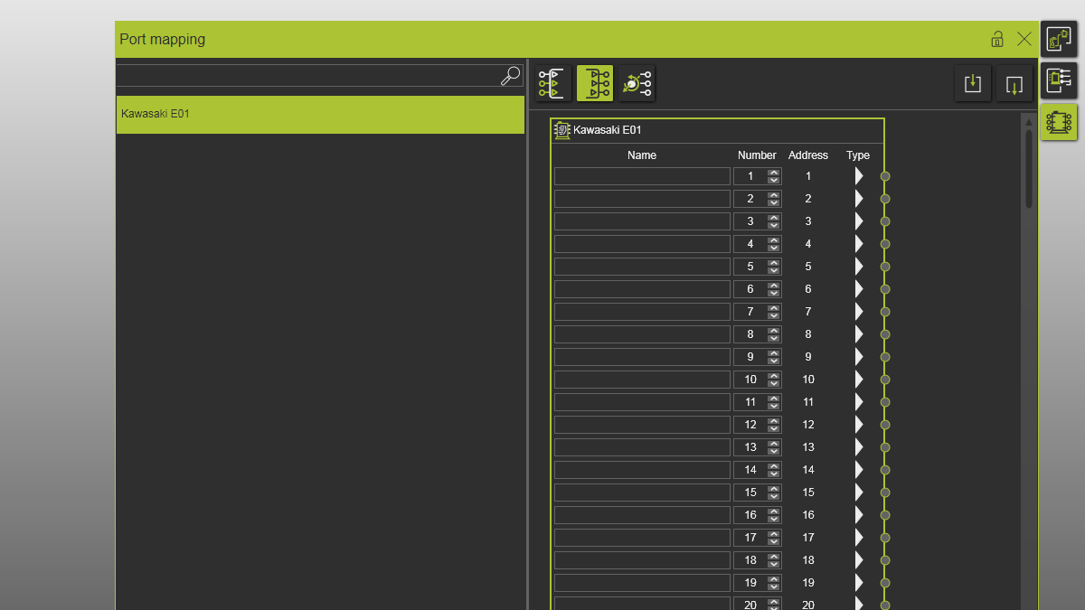
2.1 Open Port mapping dashboard
Open the Port mapping dashboard from the toolbar at the right side of the 3D view.
Port mapping
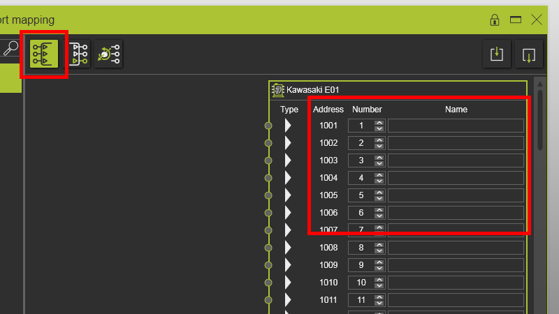
2.2 Verify empty logic out-port names
Verify that logic out-port names are empty before creating electrical connections.
Port mapping
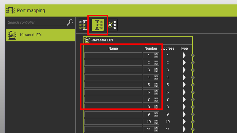
2.3 Verify empty logic in-port names
Verify that logic in-port names are empty before creating electrical connections.
Port mapping
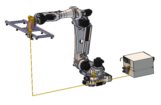
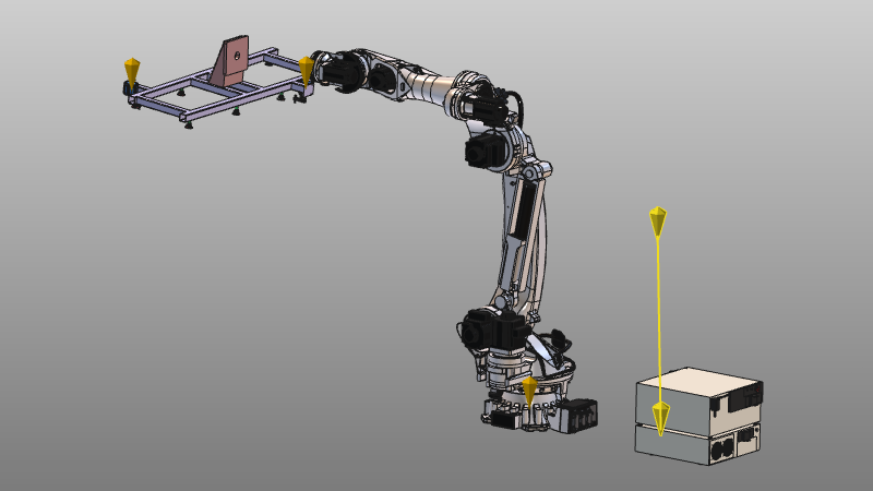
2.4 Create electrical connection between gripper and controller
Drag the electrical adapter of the gripper to the controller electrical adapter.
Create electrical connection
It is recommended to create electrical connections first, before snapping mechanical connections.
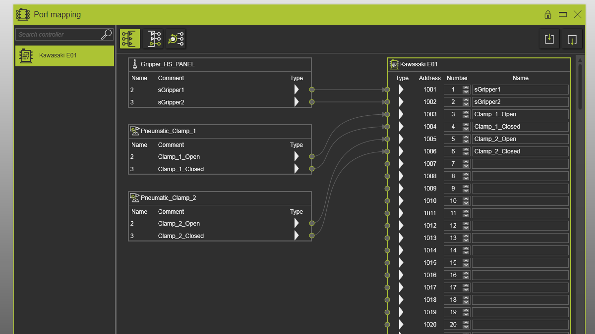
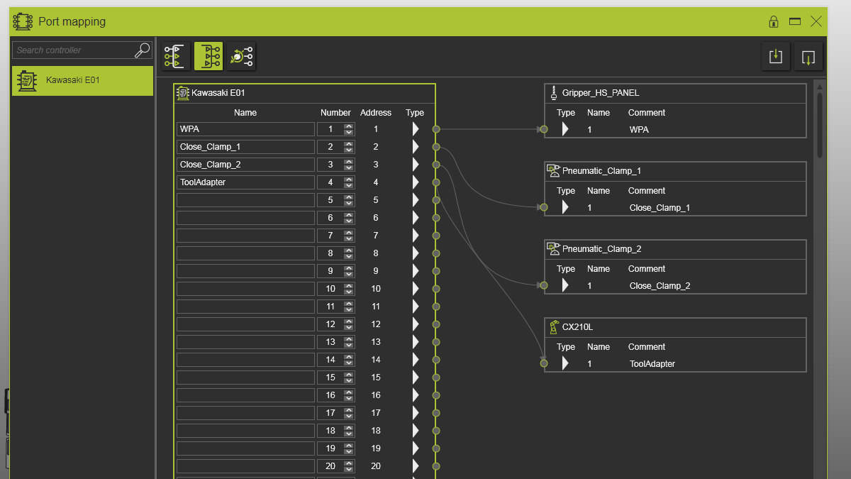
2.5 Verify automatic signal assignment
Verify that gripper and controller signals are automatically connected, and that peripheral ports are mapped to the first free controller ports.
Port mapping
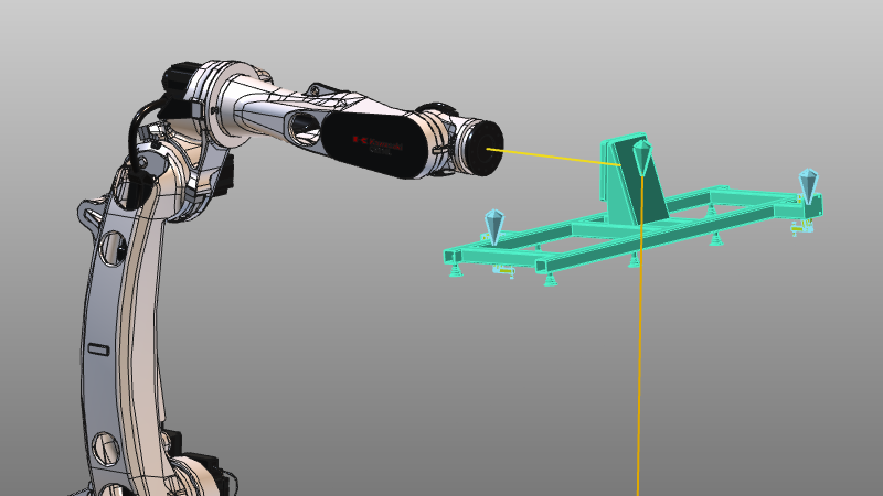
2.6 Create mechanical connection
Snap the gripper onto the robot mount plate to create a mechanical connection.
Port mapping
2.7 Verify logic out-port mapping
Verify that logic out-ports connect both to gripper clamps and to the robot tool adapter signal that indicates the gripper is mounted.
Port mapping
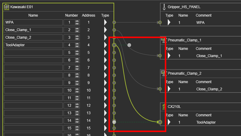
2.8 Adjust connection graphics
Select a signal connection in the dashboard and adjust curvature using its start/end direction handles.
Port mapping
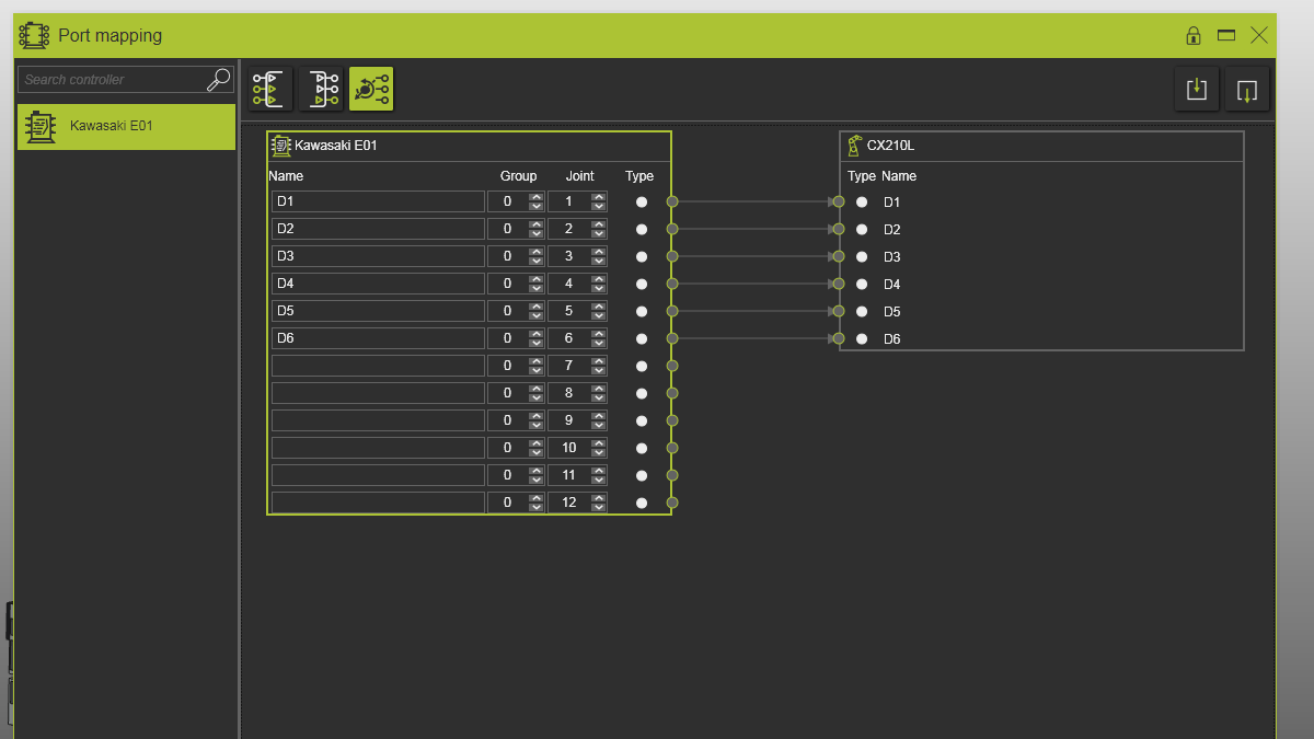
2.9 Verify joint port mapping
Verify that joint ports are connected to the robot and that port names match robot joint names.
Port mapping
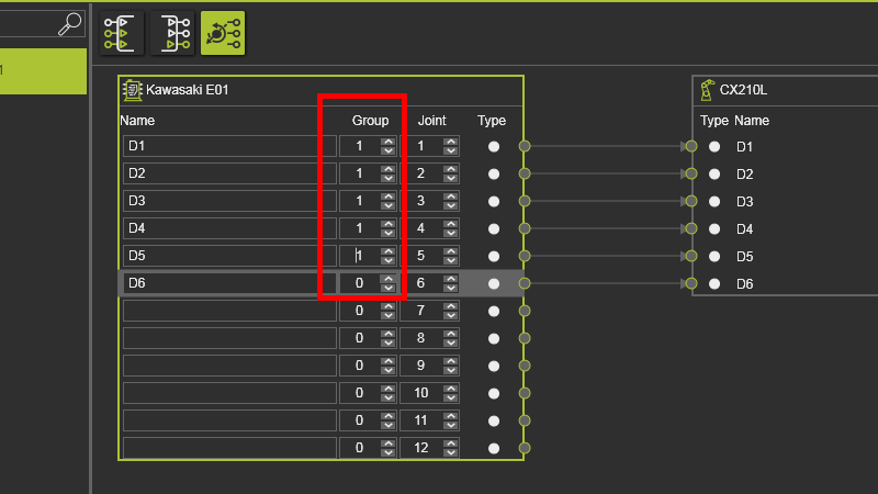
2.10 Set valid Group index
A Group index value of 0 is invalid. Change it to 1 for the first connected robot.
Port mapping
3. Save
3.1 Save the layout with mapped signals
Save layout