Build the workpiece
Purpose
Use the Workpiece Builder workbench to build the workpiece with welding positions and prepare it for offline programming.
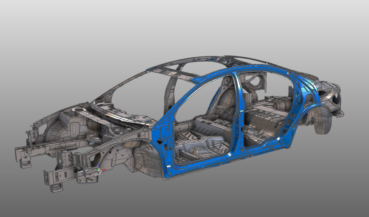
The workpiece document is created from imported geometry. Dedicated setup information and welding positions are then added so the part can be used directly in the spot welding workcell.
Steps
1. Preparation
1.1 Create a new empty document (if needed)
If another document is already open in the running session, create a new empty document. If no document is open, you can skip this step.
Create a new document
Open the File menu and select New. If prompted, choose whether to save the currently open document, close it without saving, or cancel.
2. Define the workpiece
2.1 Verify geometry import settings
To use the workpiece properly in offline programming, import the geometry as exact geometry.
Verify import settings
2.2 Import geometry from BIW_Spot_Welding_Body.cgr
Import the geometry from the BIW_Spot_Welding_Body.cgr file in the training data.
Import geometry
2.3 Create a workpiece for the imported geometry
Create a workpiece
3. Build the workpiece shape
3.1 Attach the part geometry to the workpiece
Attach geometry
4. Define the process geometry
Create process geometry elements on the welding positions.
Welding positions can be imported from external data sources or created interactively.
4.1 Import spot weld positions
Import welding positions from the BIW_Spot_Welding_Spots.xml file in the training data.
Import spot weld positions
4.2 Set process geometry mode to Point
Set process geometry mode
4.3 Create weld positions interactively
Define additional process geometry welding positions interactively on the car body with the manipulator.
Define welding positions
5. Save the workpiece
5.1 Give the workpiece an appropriate name
Name the workpiece
5.2 Save the completed workpiece
Save the workpiece