Programming toolpaths
Purpose
Learn additional functionality for programming operations and their toolpaths.
Load the project Training_LaserCutFeatures.cendoc from the Projects folder of this tutorial library.
Steps
1. Create and program cutting contours
1.1 Generate the cutting contour
Start the Generate process geometry command. Select the Generic contour mode with the Surface boundary option.
Generate process geometry
1.2 Extend selection to full surface boundaries
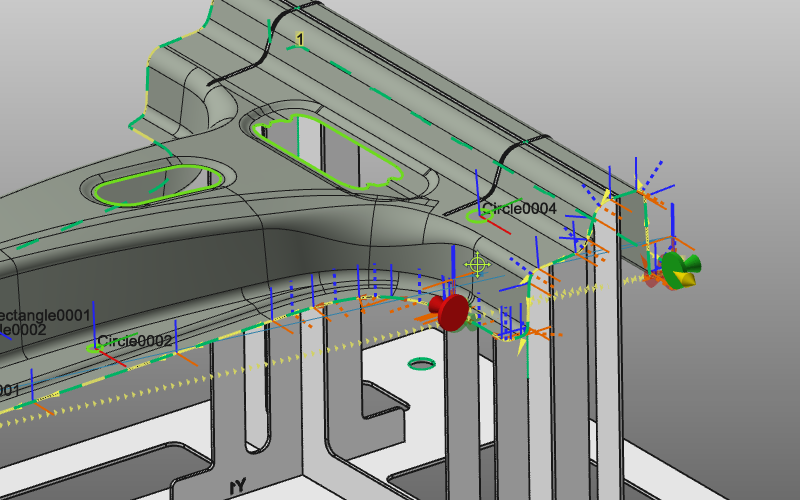
Pick a surface of the workpiece and verify that the surface boundary is marked. Open the pie menu on that surface and extend the search with Automatic surface selection. All outer and inner boundaries of the workpiece are marked with normal vectors.
Surface boundary selection
1.3 Invert normals and confirm contours
If directions are incorrect, use Invert all normals from the pie menu. Accept the result to create all cutting contours.
Invert contour normals
1.4 Program multiple contours at once
Switch to Program toolpath. Instead of computing operations one by one, select multiple cutting contours (CTRL) and program them together.
Program toolpath
2. Program sub areas of the cutting contour
Where usually the cutting contour is programmed in a single operation, it may be desired to program the contour in parts, i.e. sub areas. For example when a larger contour is being cut by two different laser robots.
2.1 Enable operation connection mode
If the Programming settings panel is not visible, open it from the pie menu. Activate Operation connection mode so programmed sub areas are automatically connected at start and end positions.
Programming settings
2.2 Program separated sub areas
Program sub areas of the cutting contour that are separated from each other.
Program sub areas
2.3 Fill the area between existing operations
Program the area between existing operations. Start and end markers are automatically placed at the neighboring operation boundaries.
Connect operation segments
2.4 Move connected start/end markers
When sub areas are connected, markers show an extra disc at start and end positions. Moving a start position automatically moves the connected end position.
Move connected markers