More welding operations
Purpose
In this chapter a second program will be created. In this program several options will be shown to complete or enhance the welding operation.
Computing additional programs is a way of managing the computed welding paths. Base information like base frames, contour directions and limits will be presented.
Steps
1. Program
1.1 Create a second program
Open the Programs dashboard and right click on Programs container when it is not open yet. Pick the Create new program command to create a second program. The second program will be automatically activated.
Create program
1.2 Verify base frame visibility
Change to Unit setup and verify that the base frames with the symbol BF are being displayed. If not, then open the Display filters and set to show all frames.
Unit setup
1.3 Create a new base frame
Right click on the robot base frame and select the Create new base frame command. The manipulator remains present on the new base frame to move it to its desired position.
Base frame
1.4 Position the new base frame
Right click on the center of the manipulator and start the Picking command. From the sub menu select the Pick center point option and select the edge of the center hole on the table to reposition the base frame. Press the Esc key to terminate the command or pick a point in the 3D space.
Base frame
1.5 Rename the new base frame
Right click on the newly created base frame and select the Rename frame command. Enter the new base frame name. Click in the 3D space to terminate the command.
Base frame
1.6 Set the new base frame active
Right click on the newly created base frame and select Set active base frame. This base frame will then become the reference for the coordinates of the toolpath elements.
Base frame
Be aware that the base frame created here is an element of the project and in that perspective will be stored in the project document. When it is required that the base frame is saved with the table, it has to be created in the table resource document with the functionality of the Resource Builder workbench.
2. Program welding operations
2.1 Create a fillet weld by projection
Change to Generate process geometry. Create a new fillet weld by projection. The end point on the seam contour that lies closest to the swipe selection determines the default beginning and direction of the seam contour. Once the preview is shown, click on the purple arrow at the beginning on the contour to change its direction. Accept the contour and compute the welding path.
Welding path direction
2.2 Combine projections into one fillet weld
Create another new fillet weld on the first edge. When the projection cannot be found, first select the edge and continue with picking the surfaces. Then continue for a second projection on the adjacent edge. Both found results will be joined to a single fillet weld. When the projections are separated, a linear connection will be created in between. Complete the welding contour and confirm to compute the welding path.
Combine multiple contours
2.3 Adjust welding path limits
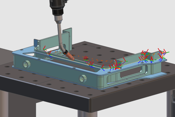
Welding operations can also be programmed on existing process geometry or when the welding path has not been computed instantly. Create a new welding seam. Once the preview is shown change to Program toolpath. Then move the green cone to change the beginning of the path and move the red cone to change the end of the path. Accept and create the welding path. The yellow cone represents which side the contour should be approached.
Welding path limits
2.4 Simulate the complete program
Reset the start state and simulate the whole program.
Program simulation
3. Program a welding operation with touch sensing calibration
3.1 Configure seam calibration defaults
Open the Programming defaults dashboard. Expand the Recipes container in the Technology base tech tab. To enable seam calibration, set the method to be applied to Touch by point indication.
Seam calibration
3.2 Create and simulate touch sensing positions
If not active already, change to Generate process geometry. Create a new fillet weld. After the contour selection has been finished, click on the surfaces that will be used to define the seam calibration positions on the welding part. Based on WYSIWYG, the mouse clicks on the surface become the touch positions in the order of picking them. Compute the welding path and run a simulation to see the result.
Touch by point indication