Build a robot controller
Purpose
Use the Controller Builder workbench to define and configure a robot controller for simulation and programming workflows.
The controller document is created from imported geometry and then configured with kinematics, frames, and properties required for reliable simulation behavior.
Steps
1. Preparation
1.1 Create a new empty document (if needed)
If another document is already open in the running session, create a new empty document. If no document is open, you can skip this step.
Create a new document
Open the File menu and select New. If prompted, choose whether to save the currently open document, close it without saving, or cancel.
1.2 Switch to the Controller Builder workbench
Switch to Controller Builder
2. Define the base controller resource
2.1 Import controller geometry
Import the geometry from the training file set.
Import geometry
2.2 Create the production resource
Create a new production type resource for the imported geometry.
Create production resource
3. Configure controller kinematics
3.1 Define the rotational joints and axes
Define axes 1 to 6 as rotational driven joints according to the available robot data.
Define joint axes
4. Attach geometry and set controller properties
4.1 Attach geometry to root and axis frames
Attach imported geometry to the root and corresponding axis frames.
Attach geometry
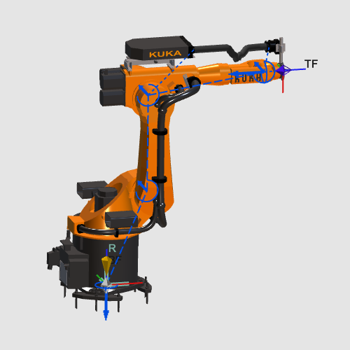
4.2 Configure TCP, frames, and controller properties
Define the tool center point, configure axis parameters, and set adapter and frame properties.
Configure controller properties
5. Save and verify
5.1 Save the controller resource
Save resource
5.2 Reload and verify the setup
Open the saved resource and verify the configured behavior.
Open and verify