Modify the cutting path calculation attributes
Purpose
Learn to modify the cutting path calculation attributes and verify how each parameter affects the generated toolpath.
Load the project Training_LaserCutFeatures.cendoc from the Projects folder of this tutorial library.
Steps
1. Cutting path calculation attributes
1.1 Generate process geometry
Start the Generate process geometry command. Select the Generic contour mode with the Search to close option. Pick a contour on the workpiece. Accept the selection and press Accept again to build the cutting contour.
Generate process geometry
1.2 Program the toolpath
Switch to Program toolpath. Select the contour and use the green cone to move the path start position. Then program the toolpath for this contour.
Program toolpath
1.3 Set approximation mode to linear
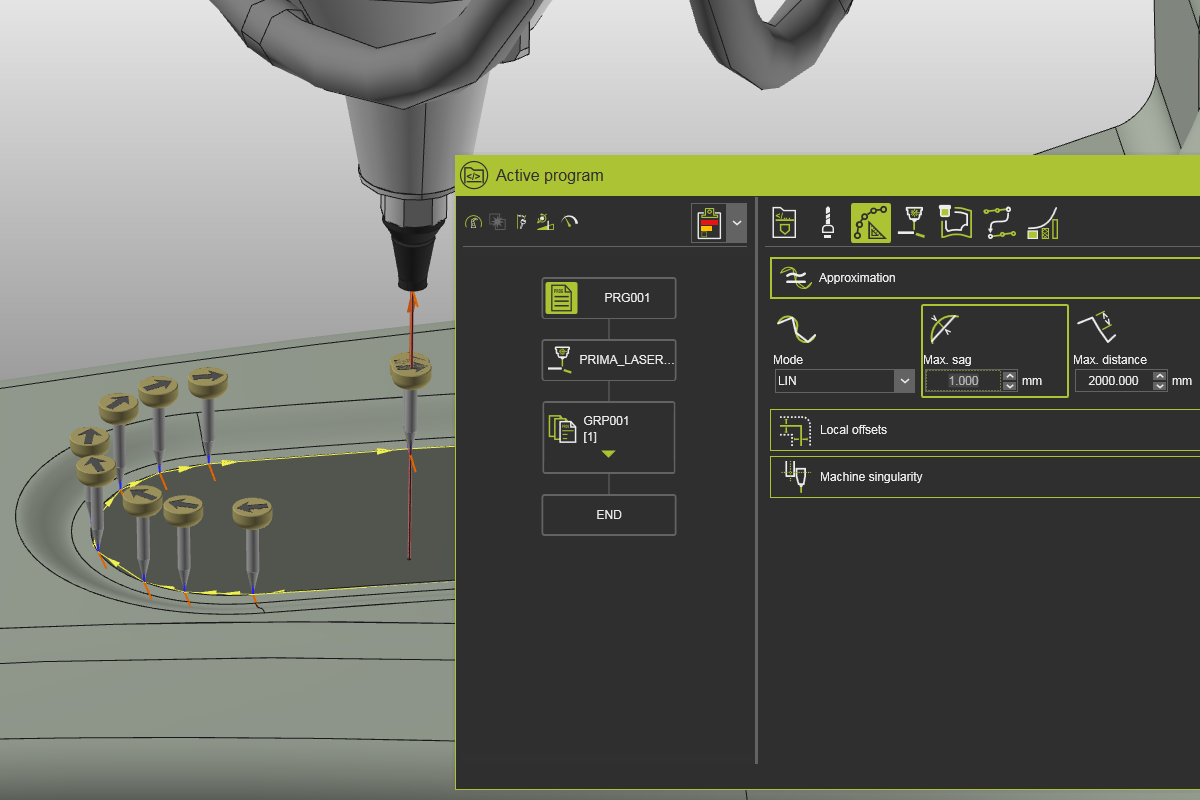
Open the Active program dashboard. In Toolpath calculation > Approximation, set Calculation mode to LIN (linear) to represent the contour with small linear motions.
Toolpath calculation attributes
1.4 Set Max. sag to 1 mm
Change the approximation attribute Max. sag to 1 mm. This defines the maximum allowed deviation of the calculated cutting path from the process geometry contour.
Approximation settings
![]()
1.5 Set maximum distance to 10 mm
Reset the approximation settings. Then change Maximum distance between path positions to 10 mm.
Approximation settings
![]()
1.6 Set sheet offset to 4 mm
Open the Local offsets container. Set Sheet offset to 4 mm and review the result.
Local offsets
![]()
1.7 Set contour offset to 2 mm
Set Contour offset to 2 mm and compare it with the sheet offset behavior.
Local offsets