Workbenches
Overview
![]()
The following workbenches are available:
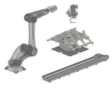
| Resource Builder |
| Resources basically are the virtual 3D representations of any real physical objects. In the context of Edition 2 resources are those objects that play a static or dynamic role in the digital factory layout to support the definition, programming and simulation of a process for manufacturing, material handling or logistics. From that point of view resources can be any device, machine, tool and equipment or even humans. A resource usually is built from some 3D CAD geometry. According to its role in the digital factory layout it is extended with kinematic and / or material flow definitions, physical properties and a set of adapters, the objects to connect the resource to other resources and controllers in the layout. |
| Commands | Dashboards |
| Select a resource | ||
| Build the resource | ||
| Resource geometry | ||
| Resource adapters | ||
| Sensors and material flow | ||
| Save the resource |
| Resource properties | ||
| Home positions | ||
| Actors | ||
| Resource behavior | ||
| Material flow properties | ||
| Tool process behavior |
| Controller Builder |
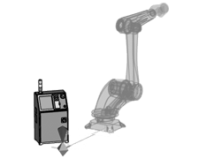
Controllers are the (3D) representation of the devices that manage (control) the different resources, or other controllers, in their operational tasks. All handling activities are under the supervision of the controller, where the controller manages only single resources, like in a manufacturing unit, or manages multiple resources and other controllers at once, like in a work cell or manufacturing line.
The managing instructions of a controller are stored in controller programs. They can be either logical or numerical.
Numerical controllers have a motion planner to calculate the behaviour of a kinematic resource. These controllers are called Unit Controller.
Logical controllers operate with signals only to trigger other logical controllers or unit controllers.
The resources and other controllers that need to be managed are connected to a controller through an electrical link to establish the communication lines. This communication is based on signals to drive actors and to receive feedback signals.
| Commands | Dashboards |
| Select a controller | ||
| Build the controller | ||
| Controller geometry | ||
| Controller adapters | ||
| Save the controller |
| Controller properties | ||
| Simulation & connectors | ||
| Process tables |
| Workpiece Builder |
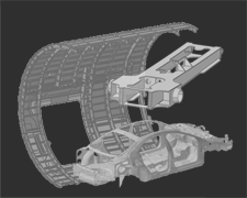
A workpiece is the component for which the manufacturing, assembly, logistic or any other process is generated and simulated.
A workpiece usually is built from some 3D CAD geometry. This geometrical information will then be enhanced with additional attributes to optimize it for the usage and simulation within Edition 2. Like other components, a workpiece will have an adapter to connect it to other components in the assembly to define its intended position. The geometrical shape of the workpiece can be extended with additional attributes and properties.
| Commands | Dashboards |
| Select a workpiece | ||
| Build the workpiece | ||
| Workpiece geometry | ||
| Workpiece process geometry | ||
| Process simulation on a workpiece | ||
| Workpiece adapters | ||
| Workpiece union and variants | ||
| Save the workpiece |
| Workpiece properties | ||
| Process geometry properties | ||
| Process simulation object properties | ||
| Process simulation object imaging |
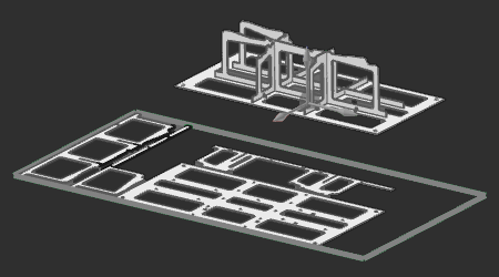
| Fixture Builder |
| Fixtures are resources that usually have one simple function: to support and carry workpieces or assembled workpieces during some manufacturing or other operation. There are many different types of fixtures, from simple product support up to extended functionality with various kind of fixation and clamping utilities. One type of fixture is designed and built from 2D plates. Support plates that carry the product are assembled together through interlocking the plates to build a stable structure. Placing this assembly in several slot holes on a base plate completes the fixture.These cost effective plate based fixtures are easy to design and can be manufactured and assembled very fast. |
| Commands | Dashboards |
 | Select a fixture | |
| Build the plate fixture | ||
| Save the fixture | ||
| Build a plate nesting sheet | ||
| Save the nesting | ||
| Utilities |
| Plate fixture property defaults | ||
| Plate fixture properties | ||
| Plate nesting properties |
| Layout Builder |
| A layout is a 3D representation of an arrangement of multiple components (resources, controllers and sub-layouts) in a virtual space. Such layout typically will be used to set up and simulate a digital factory process, or manufacturing processes. Two types of connections can be created between components: a mechanical connection to define the full kinematic system of the manufacturing equipment (usually the machine or robot and its tools), and an electrical connection between this equipment and the controller to set up the communication lines to be able to create the environment for a realistic manufacturing process programming and simulation. |

| Commands | Dashboards |
| Select a layout | |
| Compose the layout | |
| Save the layout |
| Layout properties | ||
| Workcell configuration | ||
| Signal port mapping |
| Offline Programming |
| Offline programming is the authoring method to generate controller programs for a manufacturing process and using different kinds of manufacturing technologies. Starting from a layout, the workpiece includes the generic geometrical information, called process geometry, from which the manufacturing toolpath is generated. Based upon the applied technology, the toolpath steps individually can be optimized using automatic and manual manipulation and interpolation algorithms. Enriching the toolpath with (technology specific) technical events and signal handling generates the final program for simulation and analysis. After simulation and verification a set of downloaders and uploaders are available to transform the internal data to the machine specific output. Technology packages are available for point, curve and surface based manufacturing processes. |
| Commands | Dashboards |
 | Select the program controller unit | |
| Setup the OLP project | ||
| Process geometry | ||
| Program a toolpath | ||
| Balancing & sequencing | ||
| Events & teach | ||
| Download the program | ||
| Save the project |
| Program attribute defaults | ||
| Process geometry | ||
| Program manager | ||
| Active program attributes | ||
| Toolpath monitor | ||
| Simulation monitor | ||
| Teach | ||
| Process imaging |
| Automation Builder |
| The Automation Builder is providing all necessary functions, infrastructure extensions and enhancements for the definition and use of a layout communicating with external controllers, especially for controller validation and virtual commissioning. |
| Commands | Dashboards |
| Select the program controller unit | ||
| Upload | ||
| Events & teach | ||
| Download | ||
| Save the project |
| Program manager | ||
| Toolpath monitor | ||
| Simulation monitor | ||
| Teach |
| Geometry Prepare |
| Geometry Prepare is a workbench with a toolbox of several functions and activities to assist the creation and manipulation of geometrical elements. |
| Commands |
| Axis system | ||
| Measurement | ||
| Simplify | ||
| Comparison | ||
| Assembly operations | ||
| Body operations | ||
| Face operations | ||
| Point cloud operations |