What is automatic process path optimization
Methodology
The function uses a methodology of iterative steps to find the optimal result. These iterative steps are applied to a set of variables, i.e. orientation angles of the toolpath elements that can be modified during the optimization.
In each iteration step, a range with a number of variations is being built to find the optimum result (= minimal costs) within that range. From that optimum, a new range is being defined from the variation before to the variation after that found optimum. That range again is divided in smaller steps to search for the optimum again.
This process repeats itself until the variation step equals (or is smaller than) the discretization step of the variable or when any other boundary condition has been met.
This process is executed for each of the variables. But each of these variables might give a different optimal orientation of the toolpath position. Therefore, the resulting optimized toolpath position will be a compromise between the results of the individual variables.
In the end, the automated path optimization (APO) evaluates the whole toolpath; i.e. the range (program, group or operation) that has been selected and tries to find an optimized solution that matches with the given quality criteria and then results in minimum costs.
Variation space
| By default not all attributes are being displayed. It is limited to the most common applied ones. Switching the Expert mode button at the top right of the dashboard will expand the container to show all available attributes. |
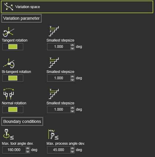
The Variation space defines what modifications can be made to the toolpath elements to search for the optimal solution. It shows all variables that can be included in the optimization process, their range within they can be varied and the distribution step or discretization within that range.
For most technologies or scenarios the default variation space values should do the job; nothing to change here when you are not that familiar with the meaning of these variables.
The variables here might be specific for a technology or a certain technology setup in combination with an OEM brand controller and robot or machine. In other words; the exact content of the container might look different for each case.
The Variation parameters describe which axis of the toolpath element may be modified.
| Parameter | Description | Optimization options | Remark | Mode | |
|---|---|---|---|---|---|
| Tangent rotation | Varies the toolpath position while rotating it around its tangent direction. | Switch to include it in the optimization process. | Expert | ||
| Bi-tangent rotation | Varies the toolpath position while rotating it around its bi-tangent direction. | Switch to include it in the optimization process. | Expert | ||
| Singularity orientation | Evaluates singularity situations of the robot or machine. In case of a robot scenario, the singularity orientation means the rotation of the toolpath position around its normal axis. | Switch to include it in the optimization process. | Expert | ||
| Normal rotation (arc welding technology) | Varies the toolpath position while rotating it around its normal direction. | Switch to include it in the optimization process. | Expert |
The Boundary conditions section includes additional parameters that can be introduced to limit the amount of variations. Where normally the tangent and bi-tangent rotation of the toolpath position can vary between -180 and +180 degrees, cause these parameters extra conditions to allow the tangent and bi-tangent axis to rotate only within the range and as long as the boundary condition is still met.
| Parameter | Description | Optimization options | Remark | |
|---|---|---|---|---|
| Max. process angle deviation | The maximum allowed process angle deviation from the reference direction. | An optimization result is accepted when the process angle is smaller or equal to this value. This value can be only edited when its corresponding criteria Process angle deviation has been disabled from the quality evaluation. | ||
| Max. work angle deviation (arc welding technology) | The maximum allowed work angle deviation from the reference direction. | Only available when the process angle deviation criteria has been replaced by separated work and tool angle criteria. | ||
| Max. travel angle deviation (arc welding technology) | The maximum allowed travel angle deviation from the reference direction. | Only available when the process angle deviation criteria has been replaced by separated work and tool angle criteria. | ||
| Max. tool angle deviation (arc welding technology) | The maximum allowed tool angle deviation from the reference direction. |
Optimization control
| By default not all attributes are being displayed. It is limited to the most common applied ones. Switching the Expert mode button at the top right of the dashboard will expand the container to show all available attributes. |
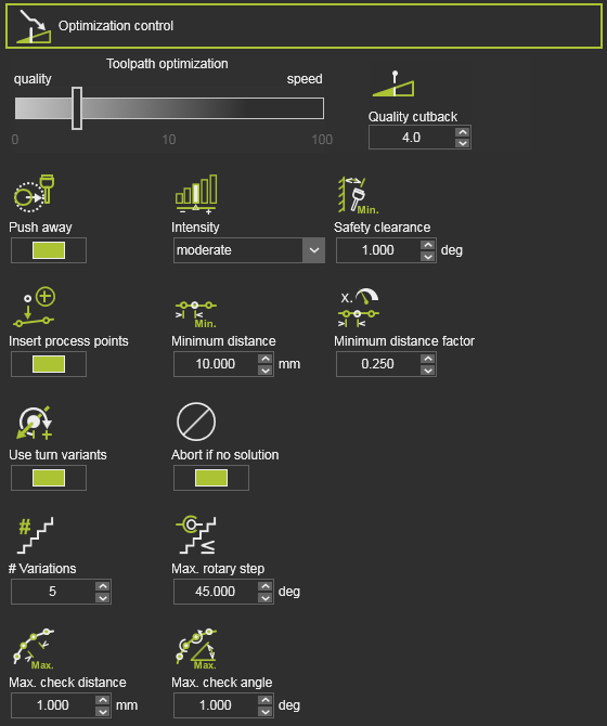
The Optimization control is a set of attributes to manage the optimization process.
| Attribute | Description | Remark | Mode | |
|---|---|---|---|---|
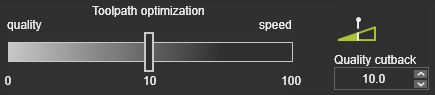 | Heuristic parameter to balance between best result and fastest computation time. | The value can be interpreted as cost tolerance per meter toolpath. A value of 0 would result in the global best result, i.e. lowest costs, regardless the required computation time. A value of 1 would mean that even a toolpath having higher costs up to 1 per meter in average would be acceptable as optimization result, though there would be better results with lower total costs. | ||
| In the standard optimization process, each toolpath position is analyzed against the collision tolerance that has been set in the simulation settings. When the initial toolpath position has collisions, the optimization tends to find a solution very close to this collision (or collision tolerance), to minimize the costs impact. With the following attributes an additional collision free requirement can be defined. | ||||
| Push away | Activates an additional optimization criterion with the goal to increase the distance between possible colliding objects. | It works as a repulsive force that attempts to increase the distance between the objects while also taking other target criteria into account. | ||
| Intensity | The strength of the repulsion effect. | Depending on the cost of other target criteria, a certain degree of strength can have different visible impacts. | ||
| Safety clearance | The minimum angular distance from collision to be maintained if possible. | If the safety distance cannot be maintained, solutions closer to the collision are also selected. A default value of 1 deg. has been set. | Expert | |
| Max. # variations | Divides the range in a maximum number of variations, i.e. step size. | Expert | ||
| Max. rotary step | The maximum allowed rotation step per variation of the robot / machine axis. | Expert | ||
| Abort if no solution | Terminates the optimization. | To prevent unnecessary long computation times, the optimization process will be aborted when on the first iteration step no solution has been found. | Expert | |
| If the resource has limited rotary axis, closed contour geometry can lead to unwind situations depending on start point and process direction. | ||||
| Use turn variants | Prevent unwind situations by selecting proper turn values for the first process point. | Limited to one turn value below and one above the default turn value. Turn variants will be not considered, if the turn value is already set for the first process point. | Expert | |
| The automatic toolpath optimization builds an optimized toolpath based on the incident validation at the toolpath positions and the via points on circular toolpath sections. It cannot prevent that in between these toolpath positions the trajectory still encounters some incident issue, because the trajectory itself cannot be evaluated. With using the motion check of the data of the toolpath, the algorithm can define intermediate points between the toolpath positions and evaluate them for incidents. The quality evaluation on these intermediate points restricts for incidents on collision, reachability and singularity. | ||||
| Max. distance | The maximum Cartesian distance between two consecutive points to be checked. | Expert | ||
| Max. angle | The maximum angular ‘distance’ between two consecutive points to be checked. | Expert | ||
| Toolpath quality is measured in costs. Incidents on toolpath positions, or between the positions normally increase these costs. The automatic optimization can identify the area of impact of these incidents. By trying to limit such area, the costs will reduce. This can be achieved by adding, inserting additional process points on the toolpath around these critical areas. | ||||
| Insert process points | Switch to enable to insert additional process points. | |||
| Minimum distance | The minimum Cartesian distance between two process points. | Measured between two inserted process points or between the inserted process point and an existing one. | Expert | |
| Minimum distance factor | The minimum distance as factor of the local process speed. | Measured between two inserted process points or between the inserted process point and an existing one. | Expert | |
| The inserted process points belong to the automatic optimization data. This means that when running another optimization, removing the optimization data or anything else that causes a recomputation of the initial toolpath, these inserted process points will be deleted. |