Program a cutting operation
Purpose
In this chapter, the fundamental steps to program a cutting operation will be taught. The basic steps generate the cutting path on different contours and simulate the results.
Steps
1. Preparation (if needed)
1.1 Switch to the Offline Programming workbench
Switch to OLP workbench

1.2 Open the project (if needed)
Open the File menu and use the Open command to load the previously saved project. If it appears in the recently opened documents list, select it there. Otherwise use the file browser.
Open a project
1.3 Select the controller unit
The first command that automatically opens is Select controller unit. Select the controller for which cutting programs will be created. When the workcell has only one controller, nothing needs to be done here.
Controller unit
1.4 Verify project setup and create a base frame
The tool frame should be at the focal point of the laser beam. A new base frame will be created on the fixture hole and set active as the program reference.
Unit setup
2. Teach a home position
2.1 Verify OLP settings
For this course, each modification to a cutting path position must be confirmed manually. Verify the OLP Settings and confirm that Apply toolpath modification is set to Manual.
OLP settings
2.2 Teach a start position
Program the first position using the Start teach command on the machine.
Teach a home position
2.3 Modify the start position
Switch to Events and teach to modify the inserted position. Use the manipulator to adjust the position, then confirm with Apply changes.
Modify the cutting path position
3. Program a cutting operation
3.1 Open the process geometry definition panel
Execute the Generate process geometry command and verify the definition dashboard is visible. If not, right-click in the empty 3D space and select Open definition panel.
Open process geometry definition panel
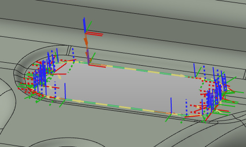
3.2 Compute the cutting operation
Set contour Search to Close and select the contour edge. The system searches for a closed contour. Accept the proposed contour, then Accept again to generate the cutting operation (or press Enter).
Compute the cutting operation
3.3 Filter the toolpath display
Use the Display filter to enhance the view.
Filter toolpath display
3.4 Modify the toolpath start conditions
The generated toolpath can be modified, including the start position or motion direction.
Modify toolpath start conditions
4. Navigate along the cutting path
4.1 Navigate to individual path positions
Switch to Events and teach. Pick any path element to make the laser head jump to it. When two elements are very close, a selector appears to choose the desired one.
Navigate along the cutting path
4.2 Simulate the program
Switch on Collision analysis and simulate the program (partially) to get a first impression.
Simulate the program
4.3 Use the Teach panel to step through the path
Open the Teach panel. Click the middle arrows to navigate forward and backward. Click the outer arrows to jump to the beginning or end of the operation group.
Navigate with the Teach panel