Preparation
Purpose
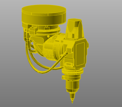
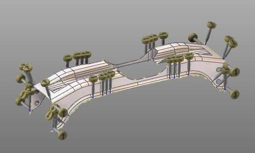
Learn how to prepare your project before running manual or automatic program optimization.
![]()
Good preparation improves result quality, reduces iteration time, and prevents avoidable optimization failures.
Steps
1. Resource setup
1.1 Verify axis limits
Check that axis limits for machine, robot, and external resources match the physical setup.
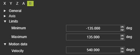
1.2 Verify axis velocity limits
Confirm maximum axis speed (velocity) values are correctly defined.
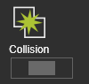
2. Collision setup
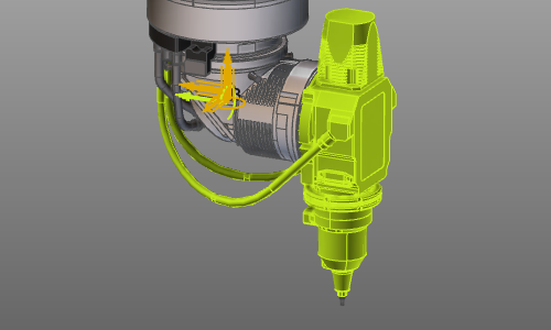
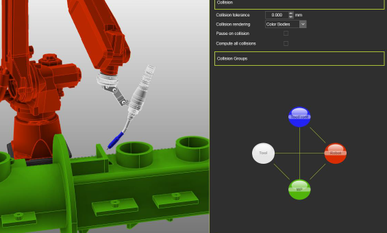
2.1 Define collision groups
Create collision groups so no permanent collisions exist between active pairs.
![]()
2.2 Exclude unnecessary geometry
Remove non-critical geometry from collision groups to reduce computation time.
2.3 Verify collision pairing
Validate collision pair definitions in Simulation settings.
2.4 Check for hidden collisions
Run a scenario check to ensure no hidden collisions remain before optimization.
3. Programming parameters
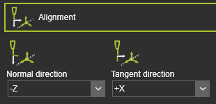
3.1 Set process defaults
Set programming defaults to the intended process state, including tool alignment and process angles.
3.2 Define clear starting positions
Program explicit start values for machine, robot, and external axes.
Include:
- External axis values at the first toolpath element.
- PTP motion to the first position in each operation.
- Approach and retract positions with the proper motion type.
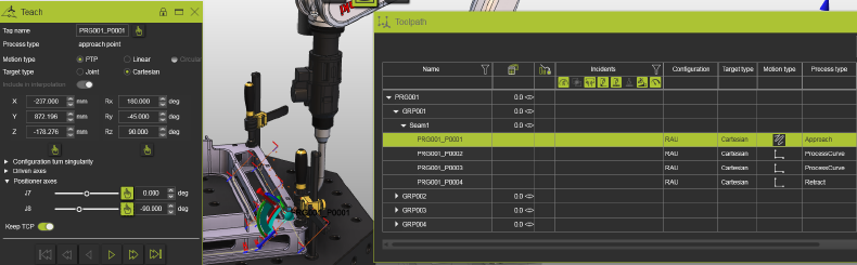
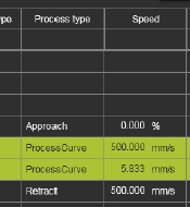
3.3 Verify speed values
Ensure process positions do not have zero speed.
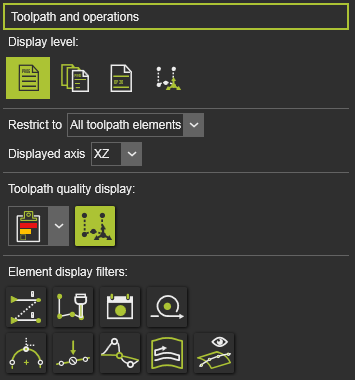
4. Toolpath quality definition
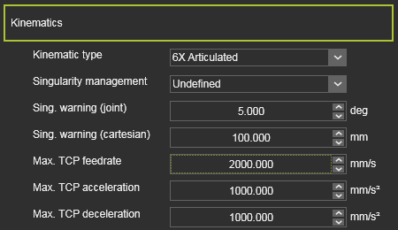
4.1 Open quality settings
Configure quality criteria in the Toolpath quality tech tab on Programming defaults or Active program.
![]()

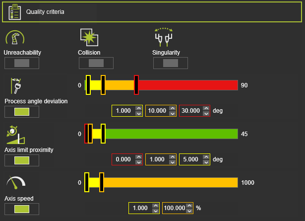
4.2 Activate relevant criteria
Enable criteria needed for your scenario. System defaults are usually a good start.
For arc welding, tool-angle criteria can be relaxed when initial tool orientation is flexible.
4.3 Tune threshold levels
Adjust limits where needed, for example maximum process-angle deviation.
Use these levels as guidance:
| Level | Indicator | Meaning |
|---|---|---|
| Start of no-go area |  | Value that must never be exceeded. |
| Start of critical area |  | Value that should be avoided if possible. |
| Start of valuation |  | Boundary where the ideal range ends. |
In most cases, keep axis-speed no-go at 100% to avoid reducing TCP speed in process sections.
5. Compute and validate the initial toolpath
5.1 Compute the toolpath
Generate the toolpath after preparation and include auxiliary start/end operations where needed.
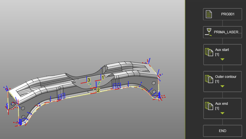
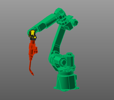
5.2 Validate in 3D and dashboards
Review the result in 3D and dashboards.
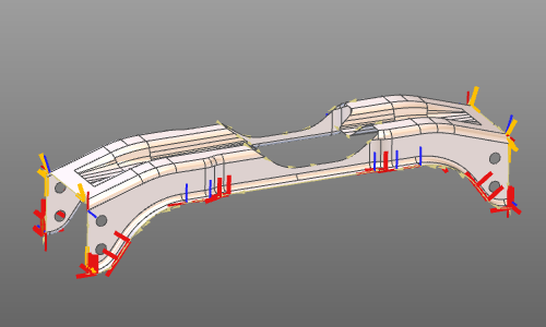
Enable display filters to see quality and toolpath-specific information.
6. Collision validation behavior
Collision validation is shown in Evaluation criteria, but activation is controlled in the simulation player bar.
Autonomous programming always runs collision analysis in the background, even when simulation collision display is off.