Generate the arc welding programs
Purpose
After setting up the workcell with the parts that are going to be processed, the welding programs can be generated, optimized and simulated.
Steps
1. Preparation
1.1 Switch to the Offline Programming workbench if it is not already active.
Switch to OLP workbench
1.2 Verify the project setup before computing operations.
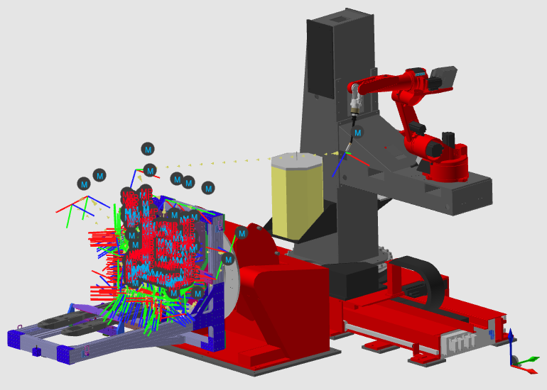
The tool frame should be located at the end of the filler wire. The base frame of the robot program at Crown usually is placed on top and in the center point of the active part positioner. And finally the arc welding technology has to be specified.
Set operation defaults
1.3 Set default welding parameters for new operations.
Typical defaults include work angle, travel angle, and welding speed. You can still adjust parameters later on individual seams.
Set operation defaults
2. Generate the process geometry
2.1 Create process geometry for welding seams if it was not created in step 2.
Create process geometry
3. Compute the toolpath
Plan the potential groups of welding seams.
Criteria to initially group the seams are:
- Expected similar positioner setup (workpiece and robot).
- Continuous motion of the robot (configuration and turns).
- Similar welding directions.
Then sequence and organize the programmed tool path in a smart way to reduce unnecessary robot movements, process seams in same direction and orientation as well as avoid high number of repositioning the workpiece positioner.
3.1 Generate toolpaths by assigning one or more seams to each operation group.
Repeat this until all welding seams are assigned.
Generate toolpaths
3.2 Give clear names to operation groups and individual operations.
Program structure
4. Organize the operation groups
4.1 Reorder operations inside each group for smooth robot motion.
Program structure
5. Optimize the operation group
Check and optimize single operation group reachability and make sure that all tool paths points of your welding program are reachable concerning the external axis robot and workpiece positioner.
5.1 Move the robot external axes near the desired welding positions.
First move the robot positioner external axis (7, 8 and 9) near to the desired welding positions.
Teach external axes
5.2 Move the workpiece positioner to ensure reachability of each seam.
Then move the workpiece positioner (10+11 or 12+13) to ensure the reachability of each seam within the group (robot snaps to the welding gun). This is not applicable, if one welding seam requires external axis movement
Teach external axes
5.3 Reorganize operation group sequence or content when required.
Reorganize the sequence and / or content of the operation groups according to initial criteria, if required.
Program structure
5.4 Review each operation and adjust where needed.
Pick each operation within the group. Modify according the activity below where necessary and step through.
Program structure
5.5 Set robot configuration and turns, preferably at the start of each operation.
Teach robot configuration
5.6 Run a partial simulation to validate current results.
Run partial simulation
6. Optimize the individual operations
Optimize the individual operations. Avoid collisions and achieve smoother and short robot motions.
Modify points if required, but minimize the number of modified toolpath elements. Modified toolpath elements become fixed and are no longer affected by technology attribute updates.
6.1 Resolve collisions by adjusting travel angle at seam start or end.
When there is collision between the weld gun and the weld part, modify the travel angle at the start and/ or end of the seam.
Modify the welding path position
6.2 Use external axis interpolation for long seams when needed.
If required due to long welding seams, use the external axis interpolation to have these axis synchronized with the robot motion.
Teach robot configuration
6.3 Run another partial simulation to validate updates.
Play a partial simulation to validate the result so far
Run partial simulation
7. Verify the collision free toolpath
Define collision free travel in between individual operations and between the operation groups by inserting additional toolpath via points.
7.1 Extend approach motions by inserting toolpath elements before existing points.
Insert points before
7.2 Extend retract motions by inserting toolpath elements after existing points.
Insert points after
7.3 Add extra via points where needed to keep transitions collision-free.
7.4 Run a partial simulation to validate transitions.
Run partial simulation
8. Simulation
8.1 Simulate the complete welding program.
Run full simulation
9. Optimize the program
Optimize the program by repeating the previous steps 4 until 8.