Modify the toolpath
Purpose
In this chapter, the operations are fine-tuned by using manual teach and manipulation functions to modify operations and transitions. Different strategies and optimization algorithms are available, and selected examples are covered here.
Steps
1. Interpolations
1.1 Run a partial simulation
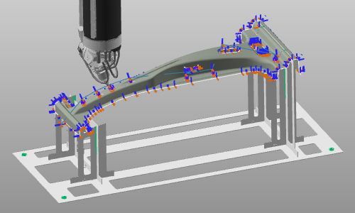
Run a partial simulation at the side of the workpiece to see how the normal position of the laser head changes while moving along the path.
Partial simulation
1.2 Create normal vector interpolation
Create a normal vector interpolation for the simulated range. Run simulation again to verify that the laser head orientation no longer changes along that range.
Normal vector interpolation
1.3 Create jolt-optimized interpolation
For smoother laser head rotation, create an interpolation over the singularity-optimized axis.
Jolt optimized interpolation
2. Optimize the toolpath orientation
2.1 Analyze collisions on the circle operation
Activate Collision analysis. Pick the circle approach position on the outer flange, open the Teach panel, and step through the operation. Observe where collisions occur.
Collision analysis
2.2 Optimize circle orientation in Teach panel
Step to the lead-in position. In the Teach panel, set head-axis rotation to A = -180 deg and B = 10 deg, then step through the operation again to verify collision-free motion.
Change toolpath orientation
2.3 Fine-tune individual toolpath positions
Toolpath positions can also be edited individually. Select a position to modify it. Besides the Teach panel, the manipulator can be used to adjust position and orientation.
Change toolpath orientation
3. Minimize laser head motion
3.1 Adjust approach and retract distances
Open the Active program dashboard and run a partial simulation for the four-hole operation group. In the Regshape tech tab, modify approach and retract distances for the group, then refine first/last operation distances and re-simulate.
Approach and retract
4. Insert auxiliary positions
4.1 Insert an auxiliary position for collision-free transition
Activate Collision analysis (if not already active). Run a partial simulation between the four-hole operations and outer contour operation, then add an auxiliary position in a collision-free location.
Insert toolpath position
5. Workpiece offset
5.1 Correct sheet offset side
If the program is computed on the wrong side of the workpiece, open Active program dashboard -> Toolpath calculation tech tab. In Local offset, set a value for Sheet offset and review the effect.
Sheet offset
6. Technology attributes
6.1 Review and update technology attributes
Open Active program dashboard -> Technology base tech tab. Verify and adjust technology attributes where needed.
Technology base
Next Step
-> Download the laser cut program