Set up the project
Purpose
In this page we will assemble a manufacturing station by using the previously created workpiece and a pre-built workcell. Learn how to hide objects by using layers. And how to set up collision groups and to prepare the project for programming the welding operations.
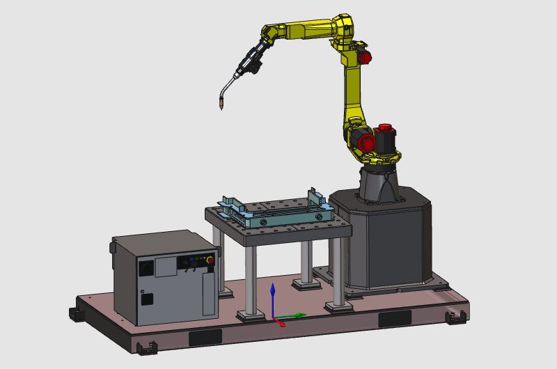
The layout will be built from some standard equipment, like the welding robot. All components will be positioned and connected together to configure the shopfloor layout. And finally the workpiece will be loaded onto the table.
Steps
1. Preparation (if needed)
1.1 Switch to the Layout Builder workbench.
Switch to LB workbench

2. Assemble the station
2.1 Add the robot cell (layout) from the Component library.
Add a layout
![]()
2.2 Add an existing workcell
When the workcell is not present in the library, it can be loaded directly from its file location with the Add existing components command.
Add a layout
2.3 Connect the workpiece to the station table
Select the workpiece with use of the Project structure dashboard. Drag the workpiece on top of the station table. Once its close to the table, a yellow connecting line between the workpiece and the table adapter appears. Dropping the workpiece now will connect it to the table.
Connect the workpiece
3. Prepare for collision analysis
Step to prepare the workcell to run a collision analysis during simulation.
3.1 Switch to the Offline Programming workbench.
Switch to the OLP workbench
3.2 Change to the Collision groups mode.
Open the pie menu with the right click on the tool and select all the geometries then create a new collision group with the selection. In the same mode select the entire robot and add it to this group. Create a new group with the table and all the component of the workpiece.
Create collision groups
![]()
3.3 Remove the welding wire from its group
Because the welding wire might always collide with the workpiece, remove it from its group.
Update collision groups
3.4 Connect collision groups
In the Simulation settings, connect the 2 groups together for the collision analysis. Then return to the Normal mode.
Connect collision groups
3.5 Switch on collision detection
Switch on the collision detection in the simulation toolbar. Then change to the Interaction mode. With the manipulator the tool frame can be taught interactively. Drag it anywhere towards the table and workpiece and watch when the geometry collides.
Interaction mode
The final collision analysis will be executed after a program has been computed. This will be taught and shown in the paragraph Modify the toolpath.
4. Save
4.1 Save the project in the same folder with the workpiece.
Save the project
Next Step
→ Generate the Welding Program