Introduction
Toolpath quality evaluation
To be able to validate the toolpath for the necessity to optimize it (partially), a toolpath quality evaluation mechanism has been implemented.
Toolpath quality evaluation is a process in which each toolpath position is analyzed and evaluated against a set of certain predefined target criteria. Criteria that have a configurable value range can be defined individually to set the value levels of the criteria, for which the analyzed toolpath result is awarded.
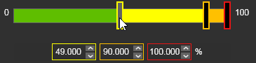
| Good (green) The value range of the criteria that is defined as good. There is no necessity to improve here. |
| Acceptable (yellow) The value range of the criteria that is defined as acceptable. Although the result is acceptable, it is advised to improve here. |
| Critical (orange) The value range of the criteria that is defined as critical. It is strongly recommended to modify, to improve the toolpath. |
| Invalid (red) The value (and above) of the criteria that is defined as not acceptable. It is mandatory to modify, to improve the toolpath. |
The following target criteria are supported, but there presence depends on the applied technology and type of machine or robot:
| Criteria | Description | Value range | Remark | |
|---|---|---|---|---|
| Unreachability | Evaluates unreachable situations of the robot or machine. | Good or invalid. | The evaluation against this criteria is always being performed. | |
| Collision | Evaluates collision situations. | Good or invalid. | The evaluation against this criteria is only being executed when the Collision analysis switch in the simulation player toolbar has been activated. | |
| Singularity | Evaluates singularity situations of the robot or machine. | Good or invalid. | The evaluation against this criteria is always being performed. | |
| Process angle deviation | Evaluates the process angle deviation from its reference value. | Angle ranges from good to invalid. | ||
| Tool angle deviation (arc welding technology) | Evaluates the tool angle deviation from its reference value. | Angle ranges from good to invalid. | It replaces the process angle deviation criteria. Only applicable when 6-axis robots are being used. | |
| Travel angle deviation (arc welding technology) | Evaluates the travel angle (tangent direction) deviation from its reference value. | Angle ranges from good to invalid. | It replaces the process angle deviation criteria. Only applicable when 6-axis robots are being used. | |
| Work angle deviation (arc welding technology) | Evaluates the work angle (bi-tangent direction) deviation from its reference value. | Angle ranges from good to invalid. | It replaces the process angle deviation criteria. Only applicable when 6-axis robots are being used. | |
| Axis limit proximity | Evaluates the proximity to the limits of the axis of the inverse kinematic chain of the (manufacturing) resource. Separated evaluation value range for linear and circular joint axis. | Linear distance or angular ranges from good to invalid. | ||
| Axis speed | Evaluates the axis speed of all driven axis as a (absolute) difference between the start and the end motion between positions. | Percentage ranges from good to invalid. |
Each position is analyzed and then is given an evaluation flag, for each criteria individually, to indicate the quality level and with that the acceptance of that position.
| Good (green) | |
| Acceptable (yellow) | |
| Critical (orange) | |
| Invalid (red) |
The toolpath quality, i.e. its incidents, is being displayed at several places.
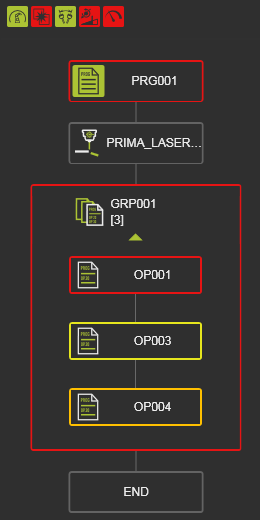 | 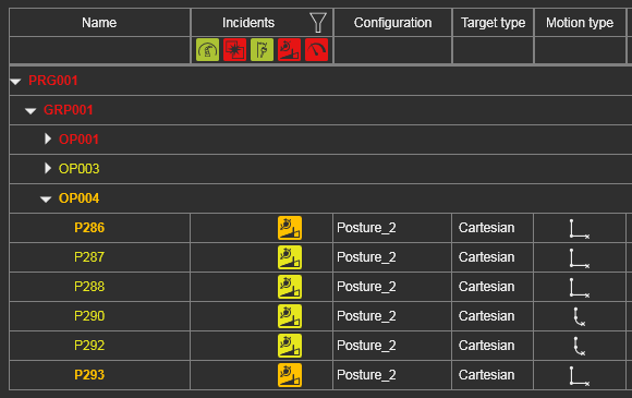 | 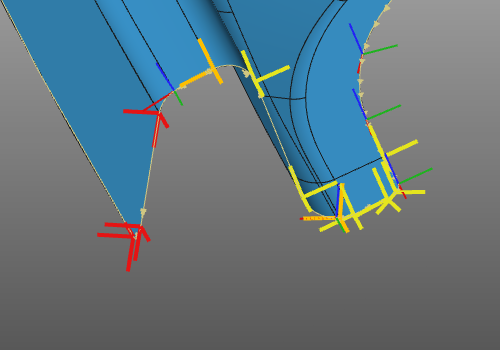 | 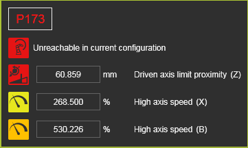 | |||
| Active program | Toolpath monitor | 3D toolpath | Incidents at toolpath position |
The quality evaluation is to validate the current state of the program. To be able to compare different states, different (quality) versions of the toolpath, a metric has been introduced; toolpath costs.
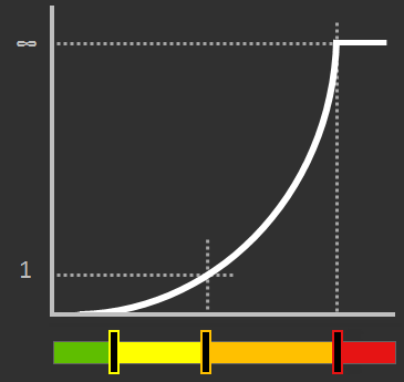
Toolpath costs is a way to express the quality in a costs factor, where each target criteria has been given a certain costs function. This can be a linear, a parabolic function or anything else, as the example below shows. It is a neutral value, not any sort of currency.
At each toolpath position the costs are calculated for each analyzed criteria and then summed up. The result is being displayed in the Toolpath dashboard and is updated immediately after any modification of the toolpath.

A trend symbol indicates the costs change compared to its previous value, the one before the last toolpath modification(s).
| Value has been increased; i.e. higher costs effect | |
| Value remained the same; i.e. neutral or no effect | |
| Value has been decreased; i.e. lower costs effect |
Program path optimization
Offline programming is normally geared towards achieving an optimal program toolpath in terms of:
-
avoiding collisions
-
keeping the machine / robot system away from singularities and axis limits
-
ensuring the reachability of the toolpath
-
aligning the process with reference values and keeping it within specified tolerances
-
running with minimal cycle time
-
fulfilling other custom guidelines.
After computing the program not always the best possible or optimal solution has been found to fulfill all the above goals. The program needs to be optimized globally or locally. This can be done by modifying the toolpath position and orientation, by editing its various attributes and parameters and by making use of the several available special attributes that assist in generation improved toolpaths.
Furthermore the software includes a set of so called autonomous program optimization functions. These functions, these methods are capable of generating and optimizing a toolpath under certain pre-defined conditions.
With this information in background one could sketch the workflow of the program toolpath creation and optimization as in the picture below.
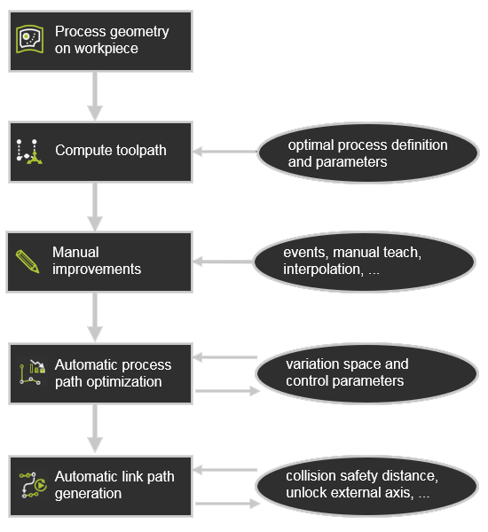
After the manual modification made by the user, the autonomous programming and optimization functionality could be applied.
The autonomous steps evaluate the toolpath and then potentially optimizes any individual position, any part of the toolpath that the specific functionality addresses. It will however preserve explicitly defined (manual) programming events and will not overwrite them, such as:
-
teach events
-
manually taught positions
-
interpolations
-
jolt optimizations
-
suppressed positions.
Autonomous program optimization
The autonomous program optimization can be executed on the whole program or just on an operation group, an operation or an operation link. It is started in the pie menu in the Active program or Toolpath monitor dashboard.
With the main command, all optimization functionality will run in the order as pictured in the workflow diagram above; first the automatic process path optimization, followed by the link path generation between the operations.

Or via the sub menu each of these can be executed individually.