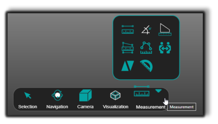
Bottom Toolbar
The Bottom Toolbar is the main interaction panel of the 3D Viewer.
It provides quick access to tools used for navigation, selection, visualization, and measurement.
Using this toolbar you can:
- Select elements in the scene
- Navigate the 3D workspace
- Switch camera projection modes
- Change visualization styles
- Measure distances, angles, and geometry relationships
Selection Tool
The Selection Tool controls how elements are selected in the 3D scene.
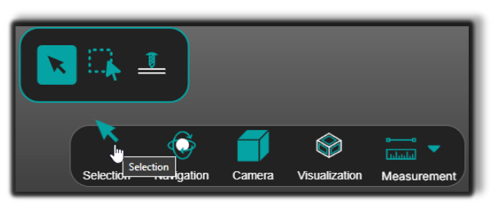
Available selection modes
- Default Mode – Select objects one by one. Ideal for precise inspection or editing of individual components.
- Area Selection Mode – Allows box selection: click and drag to select multiple objects simultaneously. Useful when working with grouped elements or applying transformations to several parts at once.
- Ray Drill Select – Selects objects along a virtual ray cast from the camera through the cursor. Instead of picking just the first object, this mode identifies all objects intersected by the ray.
💡 Tip: Use Area Selection when working with multiple parts.
Navigation Modes
Navigation modes allow you to explore the 3D environment.
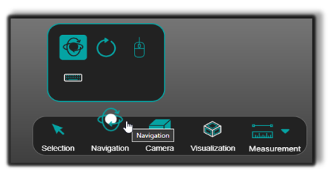
Provides free navigation inside the scene.
| Control | Action |
|---|---|
| Left mouse button + drag | Rotate the view |
| Mouse wheel | Zoom toward the cursor |
| Mouse wheel + drag | Pan the scene |
| Right mouse button + drag | Dolly zoom |
💡 Tip: The pivot point defines the center of rotation.
Rotates the scene around a fixed vertical axis.
Provides first-person navigation using the mouse.
Provides first-person navigation using keyboard controls.
Camera Settings
Camera settings control how the 3D scene is projected.
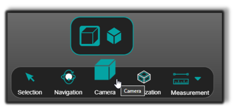
Perspective View
Provides realistic depth perception.
Orthographic View
Maintains true dimensions without perspective distortion.
💡 Tip: Use Orthographic View when performing measurements.
Visualization Settings
Visualization settings allow you to change how geometry is displayed.
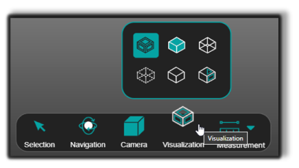
Rendering modes

Shading – Displays shaded faces without edge lines.

Tessellation edges – Displays only mesh edges.

X-Ray – Makes surrounding geometry transparent while keeping selected objects visible.

Gooch – Applies mid-tone shading that highlights edges.

Toon – Displays stylized shading emphasizing object contours.
Shading with edges – Renders faces and outlines, offering a clear and detailed view of geometry.
💡 Tip: Use visualization modes to reduce clutter when inspecting geometry.
Measurement Tools
Measurement tools allow you to check dimensions directly inside the 3D Viewer.
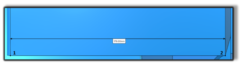
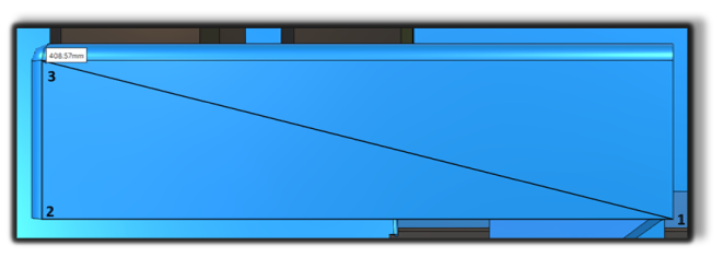
Point-to-Point Distance

Point-to-Point Distance – Measures the distance between two points.
How to use
- Select the first point
- Select the second point
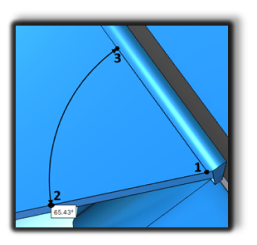
Line-to-Line Angle

Line-to-Line Angle – Measures the angle between two lines.
How to use
- Select the intersection point
- Select the first line
- Select the second line
Edge Length

Edge Length – Measures the length of an edge. For circular edges, the radius is displayed.
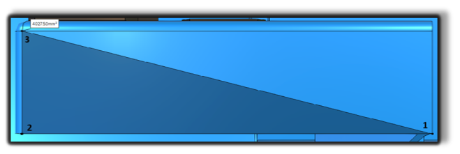
Polygon Area

Polygon Area – Measures the area of a user-defined polygon.
Polyline Distance

Polyline Distance – Measures the total length of a polyline.
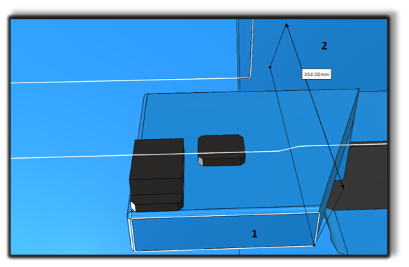
Body-to-Body Distance

Body-to-Body Distance – Measures the minimum distance between two bodies.
Face-to-Face Distance

Face-to-Face Distance – Measures the minimum distance between two faces.
Face-to-Face Angle

Face-to-Face Angle – Measures the angle between two faces.
Notes for Operators
- Use Area Selection when inspecting multiple objects.
- Switch to Orthographic View when performing measurements.
- Vertex snapping is enabled by default. Hold Alt to disable temporarily.